The famous German architect Ludwig Mies van der Rohe reportedly said, “God is in the details.”
Others have morphed his words into another saying: “The devil is in the details.”
While more pessimistic, the latter reflects the reality that when things go wrong, the culprit often turns out to be a seemingly minor detail.
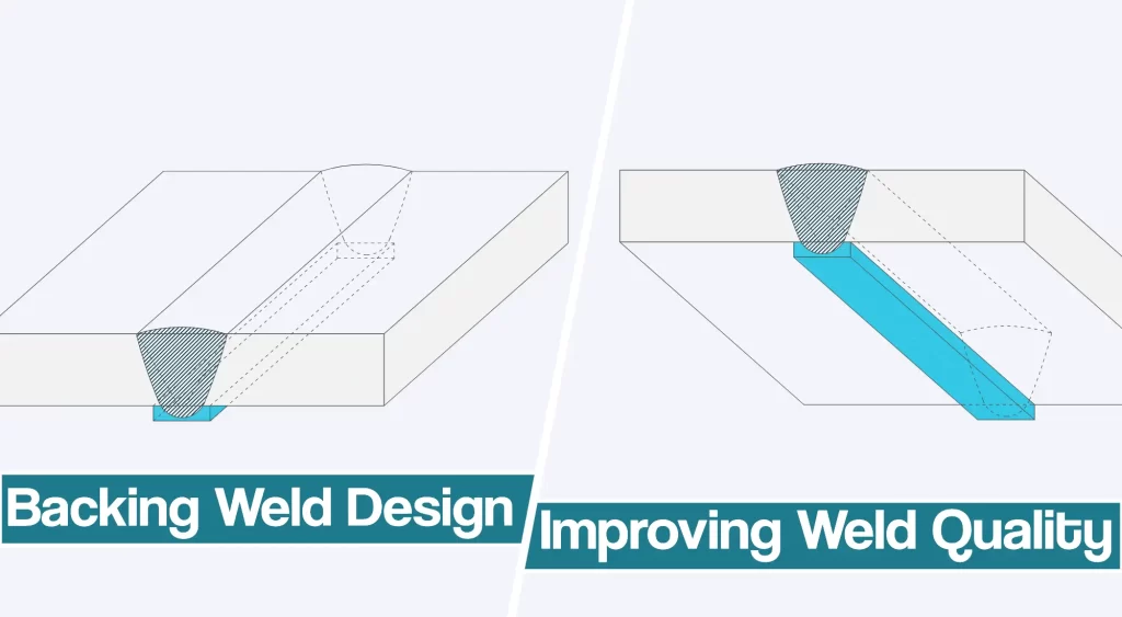
When it comes to weldment design, it is certainly true that details are critical. In this feature, we will examine one such detail backing weld design and what precautions to take so that this helpful detail does not create unexpected harm.
What Is Weld Backing?
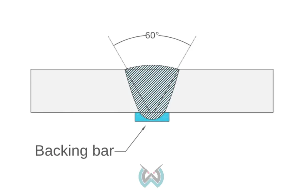
Weld backing is an auxiliary piece of material that is used to support and retain molten weld metal, as shown in Figure 1.
Backing may be fusible or non-fusible, depending on whether the weld is intended to bond to the backing. Ceramic is an example of non-fusible backing.
This discussion will deal with fusible backing.
For simplicity, we will assume that steel is the base metal being joined, and thus the backing is also made of steel.
While the proper terminology is simply “backing,” a whole range of colloquial terms are used, including “weld backing,” “backing bars,” and “backing strips.” You can learn more about backing weld symbol here to understand it in more detail.
Backing typically is associated with complete joint penetration (CJP) groove welds made from one side. The use of backing permits successful welding of joints with irregular root openings.
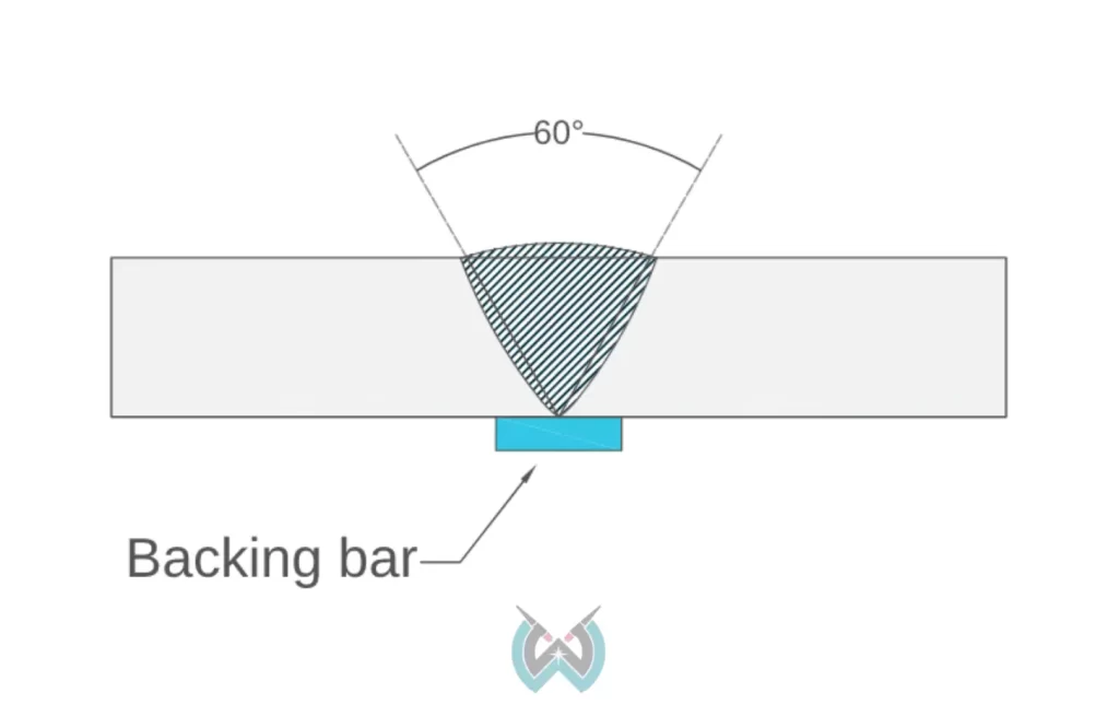
Steel backing is fusible backing; the weld metal is intended to fuse with the backing material, as shown in Figure 2.
When steel backing is left in place after the weld is completed, it becomes part of the final structure.
Because there are no secondary members in welded design, it is imperative to consider the potential influence of the backing. Left-in-place steel backing may introduce unintended load paths, or may create unanticipated and unacceptable stress raisers.
Materials For Fusible Weld Backing
Fusible backing should be made of materials that are similar to the base metal being joined.
Various kinds of unacceptable materials have been inappropriately used over the years, including grades of reinforcing steel with problematic weldability.
Thickness Of Fusible Weld Backing
The steel used for the backing should be thick enough to avoid melt-through. Of course, this depends on the welding process and procedure used. AWS D1.1 lists recommended minimum thicknesses.
Tacking Backing Weld Design In Place
It is best to attach the backing by tacking it inside the joint. When this is done, the tack weld becomes part of the final weld.
Where it is impractical to tack within the joint, tacks can be applied between the backing and the back side of the joint. In this case, the designer must consider the type of loading that will be involved.
When cyclic loads are applied that might lead to fatigue cracking, the tack welds should be made continuous.
Intermittent tack welds are fatigue category E details, with the lowest allowable stress range, whereas continuous welds are category B, with the the highest permissible stress range.
No Intermittent Backing Segments
Steel backing should be made to be continuous for the full length of the joint, particularly when the weldment will be subject to cyclical loading.
Consider steel backing that is parallel to the stress field in a longitudinal member, such as a box section as shown in Figure 3.
If segments of backing are used in a single joint, the intersections between the backing segments would create a stress raiser perpendicular to the stress field.
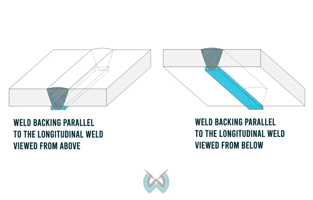
This is particularly harmful to structures subject to cyclical loading, and also can lead to problems with statically loaded applications.
If segments of backing must be used in one joint, they may be joined to each other with complete joint penetration groove welds. Such splicing should be done before the backing is attached to the steel being welded.
Creation Of Stress Raisers
Left-in-place steel backing may create undesirable stress raisers. The edge of the backing that is not fused to the thicker member creates a stress raiser.
When bending loads are applied to the thinner member, tearing or cracking can initiate at this stress raiser. In situations like this, the backing should be removed, or rotation about the weld root should be restricted.
A Practical Example
Many years ago, a customer presented me with the failed boom from a tow truck.
It had been fabricated out of two formed channels, joined at the toes with a complete joint penetration groove weld. Steel backing was used and left in place.
When I carefully examined the fractured surface, the channels showed the signs of initial fatigue cracking, followed by tearing. The initiation point was at a splice in the backing. Why, I wondered, would there be a splice in the backing?
Perhaps I don’t recall the dimensions precisely, but the booms to the tow truck were 6 ft. long, whereas the backing came into the plant in 8 ft. lengths. For each boom they made, two 2 ft. long segments of scrap were created.
In order to avoid such waste, someone decided to place three such segments end to end, and tack each length under the joint.
Thinking that the only function of backing was to aid in welding, the penny-wise but pound-foolish welder unknowingly created stress raisers perpendicular to the tensile loads that were applied to the boom when it picked up loads.
The solution was simple: Use continuous lengths of backing or, if splices were necessary, do so with complete joint penetration groove welds before the backing was inserted.
Actually, there is an even better solution: Order the bar stock in 6 ft. lengths!
Conclusion
The use of steel backing can be a very helpful production tool, allowing for quality welds to be made even when root opening dimensions are large. However, the designer must anticipate and adjust for any possible unintended consequences associated with such details.


