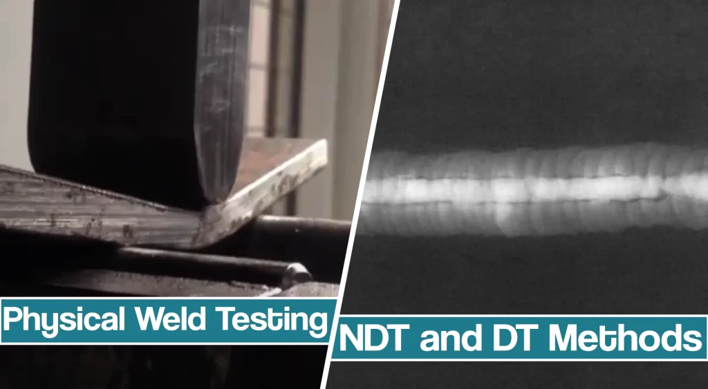
Physical weld testing is performed to check the quality of produced welds. Often, the welding procedure demands welded joints to be tested before the welded parts can be used.
There are two weld testing methods: destructive weld testing (“DT”) and nondestructive testing (“NDT”). In this article, you’ll learn about the most commonly used methods for both and their details.
Destructive Testing
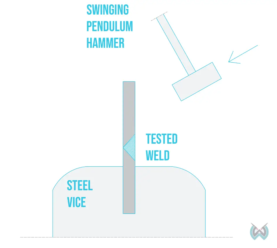
Destructive weld testing methods destroy the completed weld in the process of evaluating its physical properties like strength. Destructive testing methods are typically employed to determine qualifications, research, and analysis.
Since the welded part is destroyed in the process, it’s challenging to use destructive weld testing methods to determine if other weldments are fit for service because they are not tested.
For example, if 3 out of 10 welded parts are tested with destructive methods, and they pass the test, we cannot with absolute certainty know if the remaining 7 weldments are sound.
However, if all welded joints were created with strict procedure and operator, we can assume that the non-tested weldments are well made.
Fillet Weld Break Test
Fillet weld break tests provide a better indication of weld discontinuities along the entire joint’s length, unlike the etch test. The sample fillet weld is broken along the unwelded side using a press. Once the sample fillet weld fails, it is inspected to determine if any discontinuities are present. Fillet weld testing can detect porosity, lack of fusion, and slag inclusions.
Fatigue Testing
Fatigue testing determines how well can a welded joint handle repeated fluctuating stresses or cyclic loading. If the welds are improperly laid or contain weld defects, the welded joint will have reduced fatigue strength. Fatigue tests load the welded part to repeated changes of applied stresses until the weld fails.
Macro Etch Testing
Macro etch testing shows the penetration depth, profile, and weld’s internal structure. The welded joint is first cut into one or more samples. The weld is polished and etched at the cross-section using an acid mixture that accentuates the deposited weld metal.
Etch testing provides a snapshot of a single cross-section. To determine the weld quality overall, it is necessary to make multiple cross-sections and etch tests along the weld, but this is usually not required.
Tensile Strength Test
The tensile strength test determines the welded metal’s ability to withstand tensile force (pulling apart the metal).
The test specimens are round bars or flat strips. These specimens are cut from the center of the weld metal, which includes the weld, base plate, and the heat-affected zone.
Guided Bend Tests
Guided bend tests are most commonly performed in welding procedures and welder performance qualification tests. If the welder passes certain guided bend tests, they receive a certification allowing them to weld unlimited metal thicknesses in specified joint configurations.
This test involves bending a test specimen with a welded butt joint to a specified bend radius using plunger-type or wraparound bend test machines.
To make face bend tests, the tension force is applied to the weld face. To make root bend tests, the tension force is applied to the weld root.
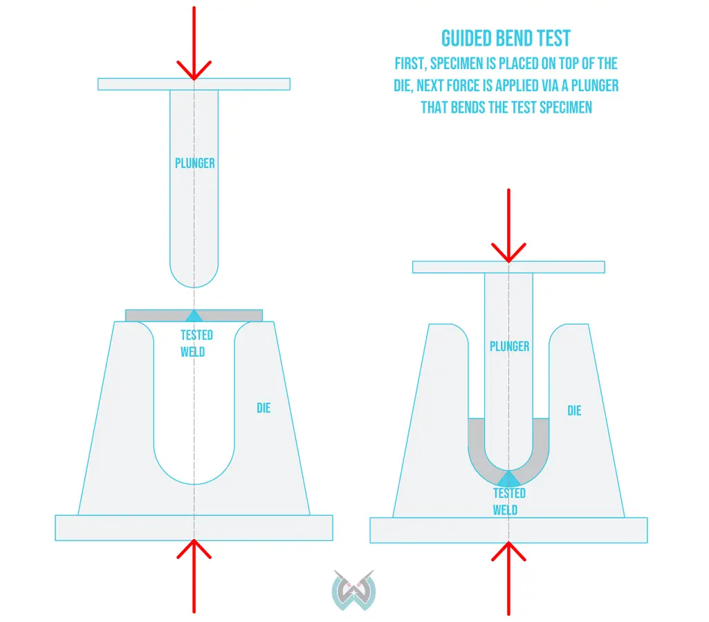
If the weld metal undergoes grinding, the grinding marks must run longitudinally to the test metal. Otherwise, the grinding marks will cause stress cracking. Additionally, sharp edges must be rounded to avoid cracks that tend to radiate from sharp edges.
Free Bend Test
The free bend test is used less often than guided bend tests because many variables are challenging to control. It’s first necessary to perform what’s called an initial bend by clamping the test bar in a vise and hammering it until it partially bends. Once the tested bar is bent enough for both ends to fit into a vise safely, the sample is bent using the vise pressure.
Non Destructive Testing Methods
Destructive weld testing methods are of no use if the welded part is in active use. For example, you cannot destroy aircraft parts, oil and gas pipes, engines, and other expensive structures and parts just to evaluate if they are adequately welded.
That’s why nondestructive testing methods are applied.
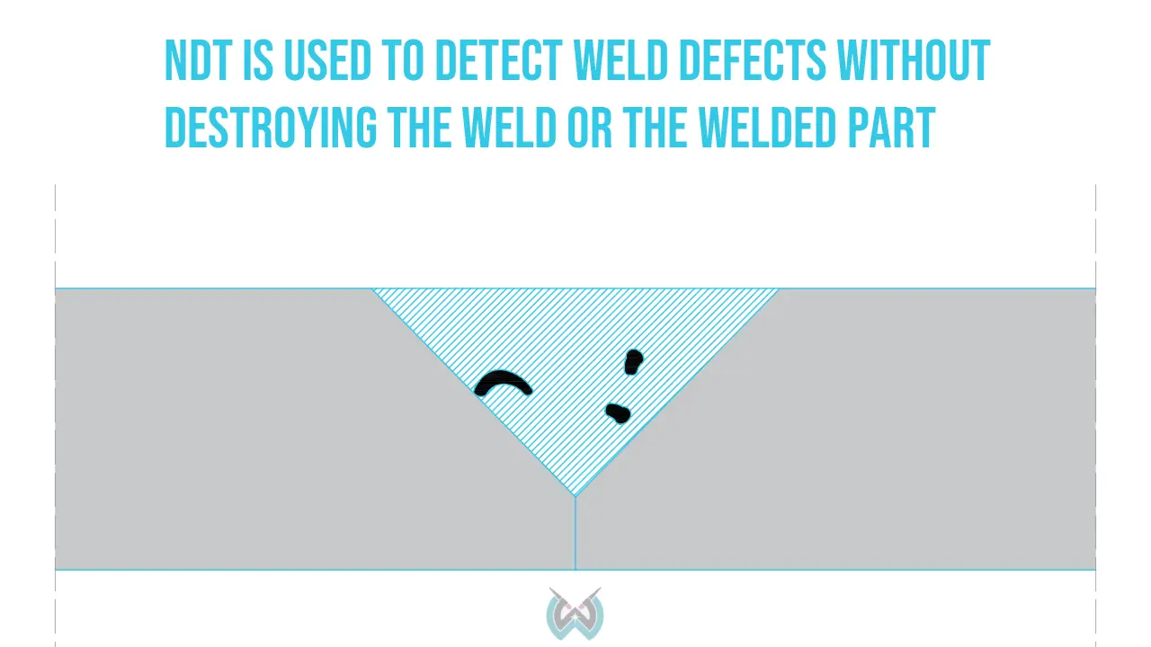
Using NDT, it’s possible to determine the material’s wear, joint quality, if the weld has developed cracks due to fatigue loads, and other issues that arise from constant use. Many industries require periodic weld testing on crucial elements, and it’s often necessary to perform NDT on welded parts before they are approved by a welding inspector.
Visual Inspection
Visual inspection is an often overlooked non-destructive testing method. It doesn’t really test the underlying weld quality, but an experienced inspector can determine if the weld should be reworked by visual inspection alone. Often, this saves time and resources. Most welds that contain discontinuities don’t need to undergo complex and expensive testing procedures if the visual inspection shows weld defects.
Magnetic Particle Inspection
Magnetic particle testing uses ferromagnetic powder to indicate defects on the open surface of the weld metal. The material must be magnetic, so this testing method is used with ferrous materials like mild steel and stainless steel.
The magnetic field is induced using an electric current after the ferromagnetic powder is applied to the tested metal.
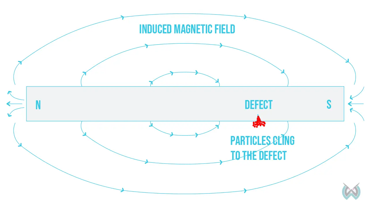
The magnetic field stays at right angles to the direction of the current flow. So, if the interruption to the current flow is present, the ferromagnetic powder detects it. Such interruptions are caused by cracks present at an angle to the direction of the magnetic poles. The powder attaches to the outline of the cracks and makes them visible.
Penetrant Method
Penetrant inspection locates the cracks and porosity near the metal’s surface. Penetrants enter into crevices, cracks, and holes and make them stand out using bright colors. The two commonly used penetrants are a bright red color and fluorescent penetrants visible under the black light.
The tested surface must be thoroughly cleaned from dust, oils, and grease. Next, the weld joint is covered with a layer of penetrant. After the specified period, the penetrant is wiped off, and a special powder is applied to the surface. This powder speeds up the process of penetrant protruding to the surface and helps its color stand out better.
Radiographic Physical Weld Testing
Radiographic testing uses x-rays for thin materials and gamma-ray tests for thick materials.
There are multiple methods of performing a radiographic test. The standard film radiography uses a plastic film sheet, just like the one used for dental radiography.
However, it’s more common now to use digital radiography or some sort of computer-aided radiographic testing methods.
X-ray testing is most commonly performed to verify if the welded joint meets the required specification before the welding inspector approves the work.
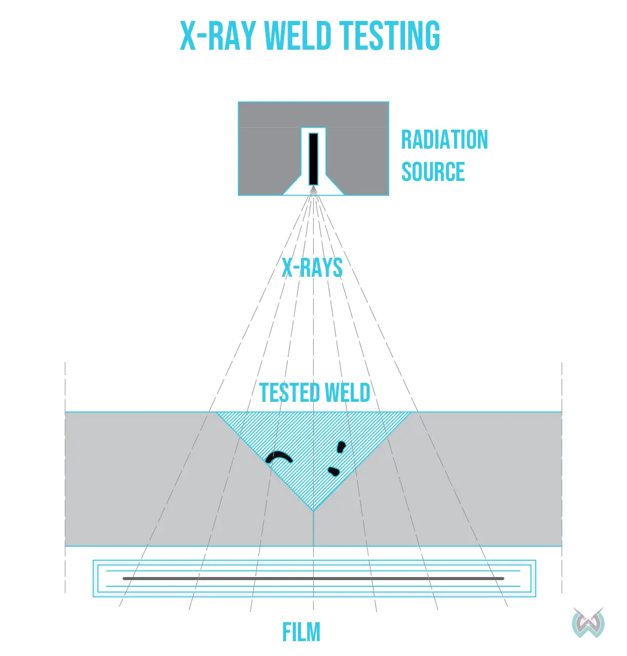
The radiography testing method works by sending the x-rays through the metal. The rays pass through the material and leave a “print” on the x-ray film. If the film shows dark spots, those are likely to be cracks, porosity, or empty space.
Ultrasonic Inspection
Ultrasonic weld inspection takes a long time to perform, so it’s often not the most economical physical weld testing method. But, it’s frequently used in welding schools because it doesn’t require many consumables.
High-frequency ultrasonic sound waves penetrate the welded metal plate surface and return back to the probe. So, if the sound is not properly reflected or not reflected at all, this means that some sort of weld discontinuity is present deep into the weld metal at that point.
The operator moves the ultrasonic probe around the base metal surface and observes the wave readout on display. The speed of sound that travels to the welded component is known in advance, so any deviation is a cause for concern with this test method.
Eddy Current
Eddy’s current physical weld testing method detects surface defects only. It cannot detect internal discontinuities like x-rays or other inspection methods.
This welding test can be performed on ferrous and non-ferrous materials.
A coil that carries a high-frequency alternating current is wrapped around the tested material, and the current is produced via induction.
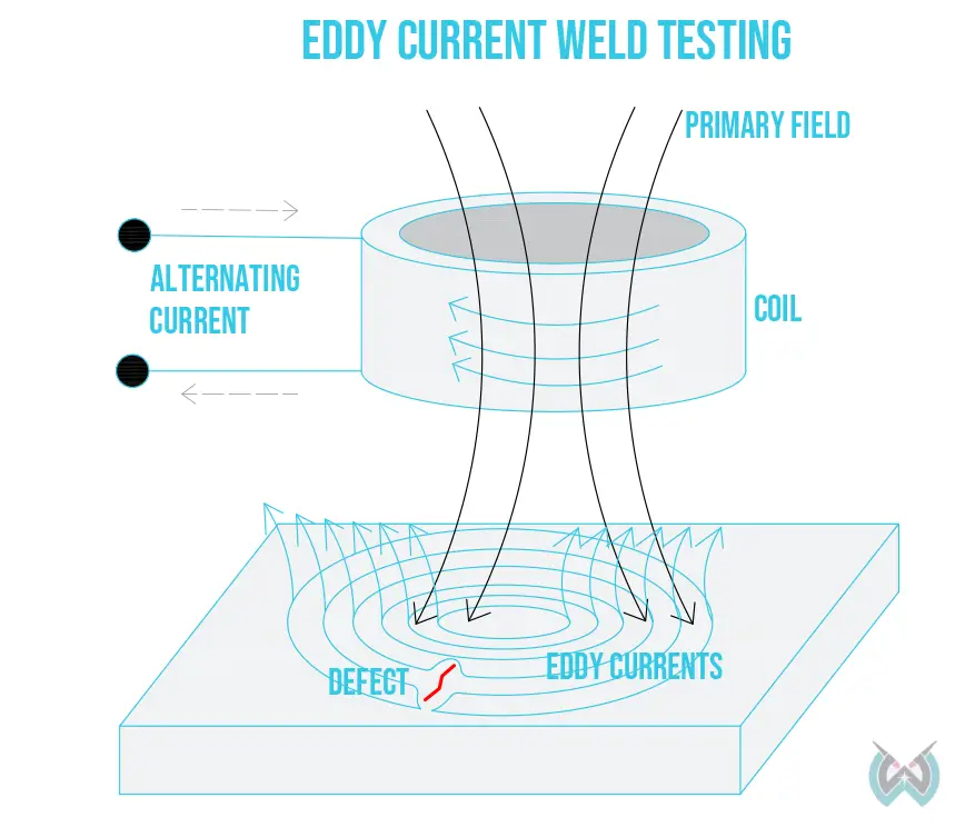
The differences in magnitude and phase result in different impedance values of the pickup coil. As a result, the operator notices these changes on the testing machine display and detects the difference in surface integrity.
Conclusion
Weld metal testing is an integral part of the welding process. Small welding jobs require only a visual test, but whenever a structural welded joint is made, non-destructive weld testing methods are employed.
If you wish to pass welding procedure qualification tests, you must pass tests like the guided bend test. Many welding certificates require passing numerous tests, including destructive weld testing and non-destructive weld testing.


