MIG welding process is one of the most straightforward processes to master, but beginners often have issues getting the settings right. You can purchase the most expensive MIG welding machine on the market, but the results may still vary.
To help you dial in your machine, we will thoroughly explain each set’s representation. Keep in mind that there are some universal rules, but most differ from a device.
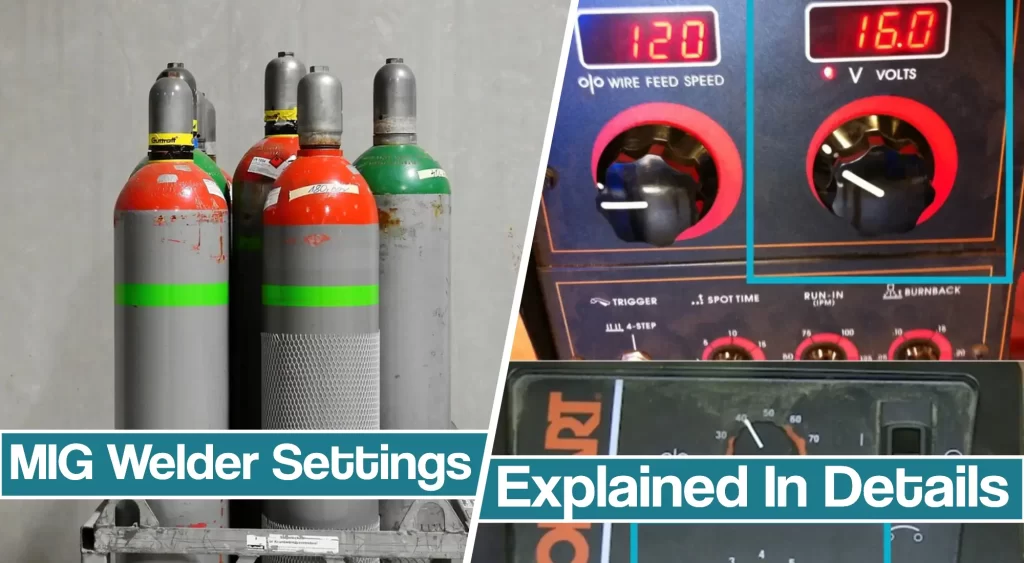
However, by understanding the basics we explained in the article, you will be able to diagnose the issue.
First Things First – Material Choice and Thickness
Before you start banging your head with MIG welder settings, you should first ask yourself – What and how thick material will you be welding?
Each material type has its unique mechanical properties.
For example, different metal alloys have different melting temperatures, tensile strength, and hold that heat differently. Therefore, there are no universal settings applicable to all material types.
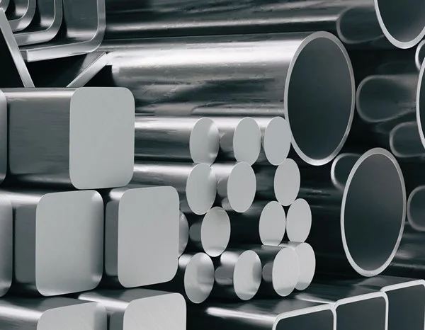
Mild steel is the most common metal, and as a hobbyist, it is most likely you will deal with it. The 0.25% carbon content is lower than medium and high carbon steels, which makes it a highly machinable metal.
On the other hand, seasoned welders might occasionally weld aluminum or work with stainless steel. Aluminum has many positive characteristics like being non-corrosive, lightweight, and is visually appealing. Unfortunately, all the positive sides of aluminum are what make it difficult for fabrication.
So before you start welding, you should consider the material you will be welding and its thickness.
How Does Material Thickness Affect MIG Welder Settings(Metal Inert Gas Welding)?
The thickness of the material might be one of the crucial things you should consider when setting up your machine.
When welding Stick or TIG, you can use nearly similar settings with different thicknesses, but with MIG, it gets tricky.
The general rule, also known as the thumb rule, states you should use 1 amp for .001 inch of material thickness. So, for example, if you are welding 1/8″ mild steel (0.125 inches thick), you should provide 125 amps.
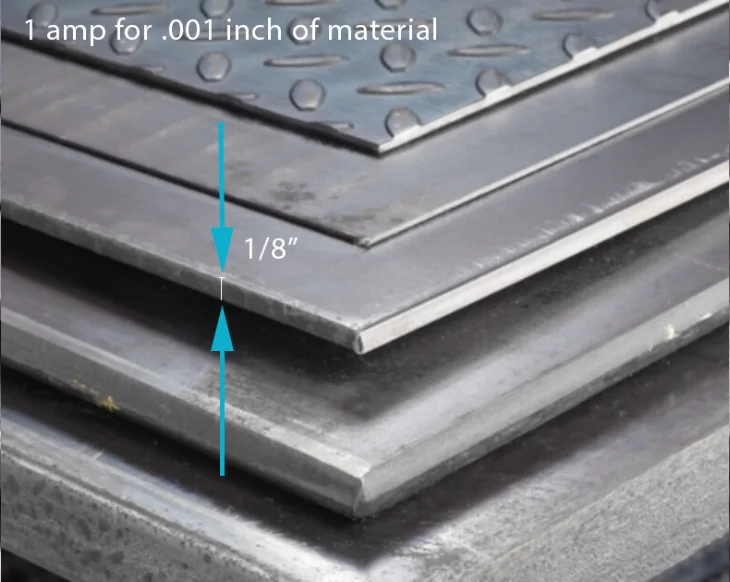
However, this rule applies to mild steel, while you will have to provide about 10-15% less current for stainless steel or 25% more current for aluminum.
In addition, there are a couple of flaws when it comes to thicker metals. So, when dealing with 1/2″ thick metals, you should provide 500 amps while following the rule. However, some manufacturers claim you can use their machines rated at 200-250 amps to do it, while the recommendation says otherwise.
Therefore, you should use the rule as a guideline for optimal performance and follow the manufacturer’s recommendations.
Shielding Gas and MIG Welding Wire
Shielding gas plays a crucial role in protecting your weld bead from defects. So before you start your welding, you will have to choose a mixture of inert gases according to a type of metal and adjust the flow according to welding conditions.
In MIG welding, you will be mostly using Argon, Helium, CO2, or a touch of Oxygen. In addition, the wire types (filler material) should suit the base metal, and here are some recommendations.
- If you are welding mild steel (carbon steel), the best choices are C25 gas type (75% Argon and 25% Carbon Dioxide) and ER70s electrode.
- As for stainless steel, C2 gas (98% Argon and 2% Carbon Dioxide) and ER308L wire type are your choices.
- Aluminum is tricky, as you will have to provide ER4043 wire with 100% Argon gas.
A high percentage of Argon or Helium added to a mix creates a hotter arc in the weld area. Besides choosing the proper type of wire, you should use an adequate filler thickness. Select one for your most commonly used thicknesses since you don’t want to change the wire.
- 30-130 amps: .023 inch
- 40-145 amps: .030 inch
- 50-180 amps: .035 inch
- 75-250 amps: .045 inch
Weld Preparation
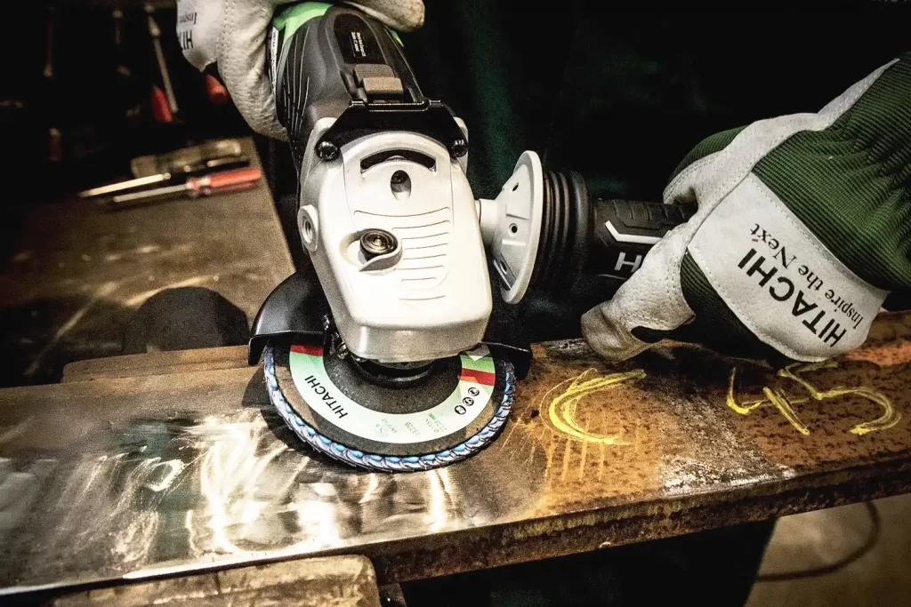
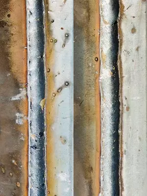
Welding preparation is no mystery as the clean welding surfaces will produce clean welds. Welder settings may differ if you work with oily, rusty, or dirty steel, so you want to ensure a clean weld.
In addition, dirty joints spatter a lot! So if you fail to clean a joint, excessive spatter may burn you or cause a fire. Settings don’t create good welds; they make good welds possible. But only if you do the rest.
That’s why you should always clean, de-scale, grind and degrease the work material before you start welding.
MIG Welding Settings: What Do They Mean?
After you have determined the thickness and type of material, selected a proper shielding gas and electrode, and cleaned the surface, it is time to set up your machine. This section will examine the voltage and wire speed and shielding gas flow.
MIG Welding Voltage Setting
MIG welding almost always uses a DC+ polarity type. The most straightforward explanation states that the voltage determines the height and width of the bead. In addition, there is a relationship between arc voltage and arc length.
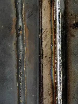
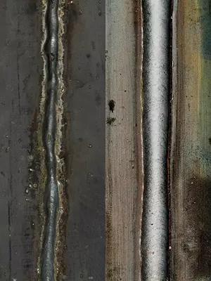
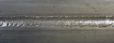
A short arc (low voltage settings) yields a narrow, ropey bead with a possibility of poor arc starts. A longer arc (more voltage) produces a flatter, wider bead.
Too much arc length makes a very flat bead and the undercut possibility.
To get the voltage straight, you should follow the manufacturer’s recommendations. For example, instruction manual or side door charts usually feature only guidelines.
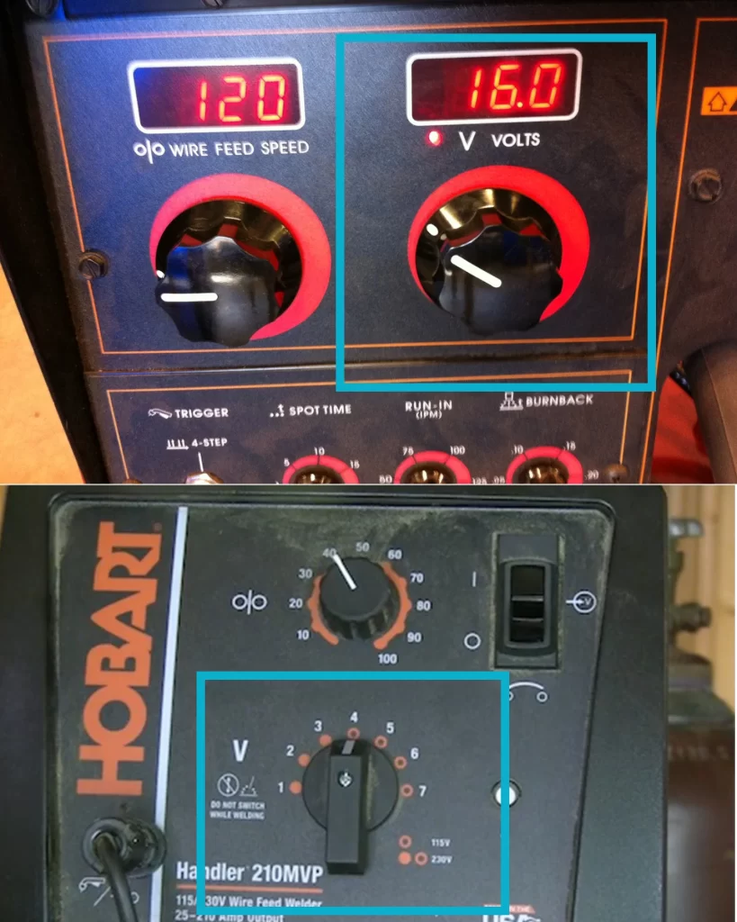
However, if there are no recommendations whatsoever (which is rare today), you should practice independently. Use a piece of scrap metal that is thick as the part you will weld, and start experimenting. Slowly turn the values up or down, until you get decent results.
You can use a sound to determine the proper voltage. Adjust the voltage until you get a nice bacon frying sound. Too little voltage and it will snub and sound like a drive-by. Too much voltage and the wire will try to burn back, or you’ll get the sound of a rattle or hiss.
Wire Feed Speed
Wire-speed controls amperage, as well as the amount of weld penetration. If you turn the wire speed up, you might have to deal with a burn-through. On the contrary, a narrow, often convex bead with poor tie-in at the toes will occur if the feed is too slow due to insufficient penetration.
Some experienced welders like to adjust wire feed speed to their preferences for different transfer type (e.g., short circuit transfer).
The instruction manual and side door chat should give you recommendations for each material thickness. If there are no guidelines, you can use our chart to serve as a starting point. For example, for .030-inch wire, multiply by 2 inches per amp, while for .023, multiply it 3.5 times.
For wire size multiply by Ex. using 1/8 inch (125 amps)
| .023 inch | 3.5 inches per amp | 3.5 x 125 = 437.5 ipm |
| .030 inch | 2 inches per amp | 2 x 125 = 250 ipm |
| .035 inch | 1.6 inches per amp | 1.6 x 125 = 200 ipm |
| .045 inch | 1 inch per amp | 1 x 125 = 125 ipm |
Gas Flow Settings
Once you set up your machine to produce fine weld quality, you should set the shielding gas flow to protect it from defects. The primary purpose of the gases and mixtures we described above is to prevent contamination of your weld. Gas flow is measured in cubic feet per minute CFM.
As for the other settings, you should experiment since the amount of flow depends on current welding conditions. For example, if you are welding in the shop or other indoor conditions, 15-20 CFM will do just fine.
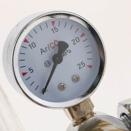
However, if you open the door or a draft present, you should turn it up to 35-40 CFM. But, keep in mind that too much gas pressure can cause turbulence and suck in air to contaminate the weld.
| MIG Gun Nozzel Size Inside DIA | Minimum Suggested Flow | Typical Flow Setting | Maximum Flow Setting |
| 3/8 in | 15 CFH | 18 – 22 CFH | ~30 CFH |
| 1/2 in | 18 CFH | 22 – 27 CFH | ~40 CFH |
| 5/8 in | 22 CFH | 30 – 35 CFH | ~55 CFH |
| 3/4 in | 30 CFH | 30 – 40 CFH | ~65 CFH |
MIG Welding Charts
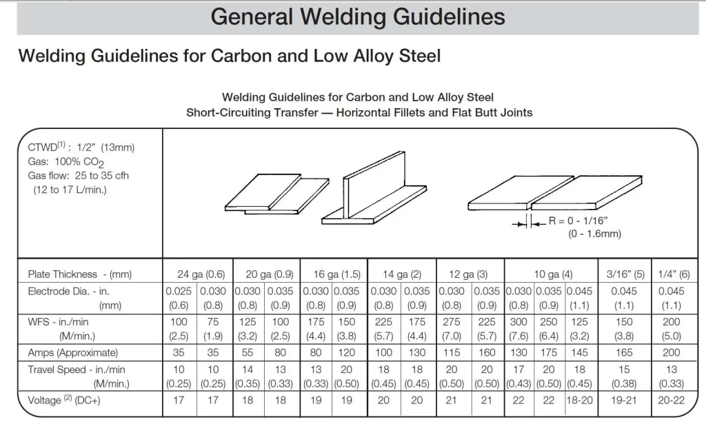
The welding chart that comes with your machine undoubtedly provides the best guidelines for the welding start. However, state-of-the-art hobbyist MIG welders such as Miller Millermatic or YesWelder MIG 205 DS feature intelligent settings.
With synergic or auto-set settings, you have to input the material thickness and MIG wire diameter, and the machine will do the rest. Auto-set is an excellent feature for beginners, so if you are tired of trying to figure out the machine settings, you should look for a MIG welder that provides it.
However, nothing beats the manual settings, as recommendations might be too hot or cold. That’s why you should always use charts and synergic settings as a guideline.
Wrapping Things Up:
First, you should consider the material type and thickness and adjust the accessories and equipment. Then you will have to clean your weld. Finally, voltage, wire speed, and gas flow settings come at last, where you combine everything you learned in this article.
To keep it as simple as possible, we pointed up many times that there are no universal settings that you can use on welding machines. So even though it might sound disappointing, understanding the controls is crucial.
Remember that setting the machine is a trial and error process. You will burn through the metal with too much heat, burn your MIG gun nozzle, or achieve poor penetration until you get it right.
If your hobby is turning into a passion, you can always consider one of the welding technician programs.
Resources
- MIG welder settings by Miller Electric https://www.millerwelds.com/resources/article-library/miggmaw-101-setting-the-correct-parameters
- Adjusting power settings by MIG welding UK https://www.mig-welding.co.uk/power-settings.htm
- MIG welder considiration by Tulsa Welding School https://www.tws.edu/blog/welding/mig-welder-setup-considerations/
- Tips for settings MIG parameters by Hobart Brothers https://www.hobartbrothers.com/2021/09/tips-for-setting-mig-welding-parameters-for-thin-materials/
- Welding parameters by ESAB https://www.esabna.com/euweb/mig_handbook/592mig7_1.htm


