Welding robots once tripped over their wire feeders.
Advances in digital control, including 50 kHz inverter switching and digital signal processors, enabled power sources to respond to sensor feedback from the arc in fractions of a millisecond.
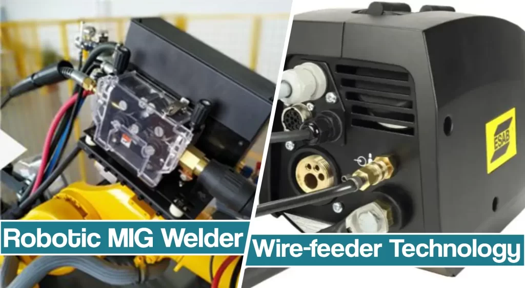
Today, wire feeder technology, combined with digital welding power sources for robotic welding, is reducing cycle times through improved start/stop times for arcs, and enhances reliability and process control.
So, let’s take a look at modern wire feeder technologies and understand how a MIG robotic system works.
Motor Control Technology
The use of either four-quadrant motor controls or servo motor technology in wire feeders has produced a ten-fold increase in start/stop performance and accuracy compared with older, semi-automatic feeders.
Manufacturers also incorporate solid-state circuitry to improve reliability and reduce costs.
The use of digital communications to link motor control boards and feed heads allows feeders with integrated motor control boards to be placed between 50 ft. and 100 ft. away from the welding machine without a loss in motor performance.
Digital communication sends more precise information such as the measurement of motor torque and the amounts of wire used even when the wire feeder is at that distance from the power source.
Some manufacturers monitor motor torque on wire feeders to detect problems such as bird nesting or clogged liners. In these situations, the welding machine sounds an alarm if pre-programmed detection levels are exceeded.
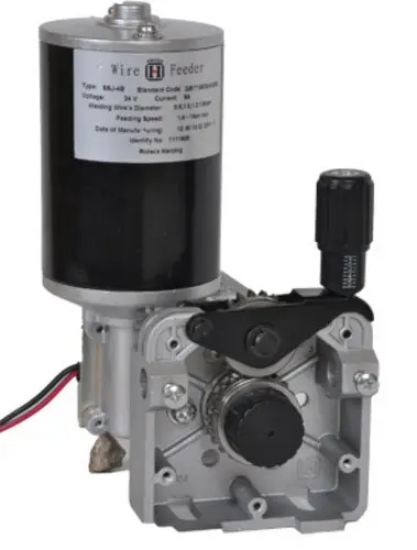
Also, monitoring the wire feeder motor’s revolutions per minute helps to keep track of wire feed speed and allows the controller to count the inches of wire used.
A feature allowing to specifying the length of wire that will be fed during the wire jog operation saves time and money. Operators can use this feature to feed wire an exact length, such as the length of a torch, with one push of a button instead of feeding the wire by pushing a button several times until the wire sticks out of the tip. Information on wire use allows the system to notify personnel when the next wire change is expected based on the weight of the wire and drum or spool, usually 500-pound or 1,000-pound packs.
Wire Feeder Performance
While welding power sources can respond in micro-seconds, arcs cannot start until the wire feeds across the gap and closes the circuit. The rapid acceleration of the wire shaves milliseconds from each arc start. However, if the wire feed speed is too fast at the start, the arc can be extinguished and violent shorts are created. To avoid this problem, most manufacturers use a lower “run-in” speed to start the arc and rapidly increase feed rates after the arc is established.
How Power Source Controls The Wire Feeder
The timing of the wire-feed motor, power source, and robot motion must be coordinated to achieve optimum results. Robot controllers usually issue the master task sequence, including where to start and stop and which weld settings to use.
The power source or weld controls control the current and voltage and manage the wire feeder. To improve cycle times and application performance, some manufacturers optimize sequencing by implementing algorithms that issue start commands to the power source at a fraction of a second before the robot reaches its targeted starting point.
This maneuver reduces cycle time, but it also can lead to violent arc starts if the wire touches the workpiece while the robot is still making a high-speed air cut move — the robot cutting across space to get to the next position for welding.
Synchronizing Push-Pull MIG Guns For Welding Aluminum
In these set-ups, a wire drive pushes the wire from the spool to the torch and another wire drive in the torch pulls the soft aluminum wire.
The motor controls allow for tighter synchronization of the drives to improve feeding reliability and to add new process variations, such as “pulsing.”
The wire feed speeds can be “pulsed” at high and low rates to create gas metal arc welding (GMAW) welds that look similar to the “stacked dime” patterns made with gas tungsten arc welding (GTAW).
Pulsing can be used to balance heat input and to create a more uniform bead width on long aluminum welds.
In addition, retracting the wire after initially touching the workpiece creates an arc start that is more reliable and produces less spatter in the GMAW process.
Arc Start And Anti-Sticking
The key to better arc starting always has been controlling the end of the wire at the end of the previous weld. More reliable arc starts are created by minimizing the formation of a ball on the end of the wire when a previous arc is completed.
Manufacturers have implemented various procedures at the end of the weld to control burnback and reduce molten ball formation. The rapid deceleration of the wire feed shortens the amount of time available for a ball to form and reduces cycle time.
Also, bringing the wire feed motor to a complete stop eliminates sticking. If the motor coasts at the end of the weld, wire may continue to enter the molten weld pool and stick. Most robots and welding equipment are equipped with “anti-stick” features.
However, having the robot controller monitor wire sticking sometimes can lead to spatter and can reduce cycle time. A better method is to have the wire feeder retract the wire toward the tip as the weld ends.
Wire Retraction Reduces Spatter In Short Circuit Welding
Synchronizing wire feeders with inverter power sources has advanced in welding.
The use of sophisticated current control algorithms triggered by feedback from the arc help to produce low-spatter, short-circuit welding.
In short-circuit welding, the current is applied to melt the wire, and it is cut back to a low level when the short circuit occurs and wire transfer takes place.
A recent development is to retract the wire during the short circuit event to “draw” the arc.
This greatly reduces the heat input.
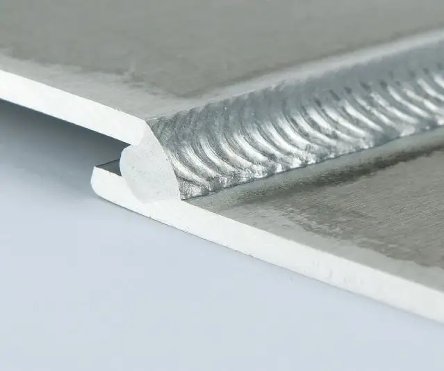
In addition, voltages are low because the arc is maintained mechanically, not electrically, and travel speeds are above 200 in. per minute on thin materials, such as aluminum and steel less than 0.040 in. (1.0 mm).
This process is called cold metal transfer welding, and it is used to weld dissimilar materials because the low heat input avoids the metallurgical factors that are presented in classic arc welding. It drastically improves weld quality and improtant weld parameters, while reducing heat input for best results.
Wire Feeder Variations
Wire feeders are light enough to mount on a robot arm. This placement reduces the feed distance and improves feeding reliability. Today, most feeders feature a “tool-less” design to make the changing of consumables easy.
Variations in feedroll configurations include V-shaped grooves that are commonly used for steel wire. Other variations include matched groove rollers that can be located on the top and bottom drives, and grooved bottom rollers that have flat, idler rollers on the top.
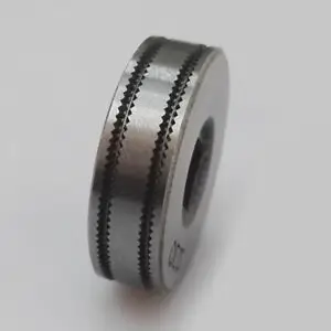
The latter configuration is less expensive because the flat roll normally wears longer. Knurled drive rolls often are used for larger diameter flux-cored wires, and U-shaped grooves are recommended on top and bottom for soft wires such as aluminum.
National Characteristics
Differences in wire feeders sometimes run along national lines.
For example, Asian markets reduce costs by using two-roll wire drives as standard equipment. Conversely, U.S. manufacturers prefer four-roll feedheads that are available usually as an option because they think those feedheads straighten wire. Straightening wire is not a critical issue with bulk wire packages that tend to have larger wire casts.
Manufacturers in Asia also use “pancake” or print motors in wire feeders because the low-inertia rotor provides quick response.
Newer wire feeders for Asian markets have replaced silicon-controlled-rectifier motor controls with pulse-width-modulation motor controls with encoder feedback from the motors.
North American wire feeder manufacturers continue to produce heavy-duty, four-roll drives that are less expensive than two-roll drives because of the volume produced. North American models also traditionally feature encoder feedback for speed control. Most wire feeders designed for robotics feature high-end motor controls, sophisticated software control, open motors for cooling and covered feedrolls to reduce pinch hazards.
European wire feeders are completely enclosed because of European health and safety product label requirements. Covers do not interfere with normal drive system maintenance on European wire feeders because of their design. The enclosures may also house the motor control boards for the feedheads to provide rapid motor response.
MIG Welding Robots Design
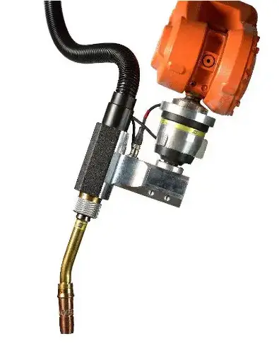
Robot manufacturers also are involved in improving the welding process. For example, to reduce downtime caused by the failure of wire feeder cables along external connection points, robot manufacturers moved the cable harnesses to inside the robot arm.
Robot manufacturers also designed robots with features unique to arc welding. These features include cabling that is integrated with wire feeders and robot castings with hollow passages through which wire is feed to the torch. These simple adaptations reduce everyday wear and tear that leads to system failures and downtime.
MIG Welding Robots Repair Tips
Robot repair technicians are dispatched sometimes to “fix” welding problems related to wire feeding. Before calling a service technician, perform this simple check:
Step 1: Grasp the wire between your thumb and forefinger, applying moderate pressure while you inch the wire forward. The feed system should continue feeding wire between your fingers. If the wire feed stops, increasing the tension on the drive rolls may solve the problem. However, too much tension will cause the drive to wear prematurely or will alter a wire’s cast as it comes out of the torch. To avoid over-tightening, use your hands, not tools, to make adjustments.
Step 2: If tension adjustments do not solve the problem, check the feed system. Release tension on the drive rolls and pull on the wire coming out of the torch tip. Heavy resistance indicates the wire feeder may be working too hard. If this is the case, disconnect the conduit at the rear of the feeder and pull the wire to check the amount of drag from the wire package. High drag into the rear of the feeder may indicate that an assist wire drive or motorized dereeler is needed because the wire must travel too far or the wire spools are too heavy. High resistance in the torch cable often indicates the need to change the gun liner.
Maintenance Tips
The above steps should be performed monthly as part of a preventative maintenance program that includes checking for signs of wear, such as metal shavings around the feedhead, deep grooves worn into the wire guides, or shavings/powder collecting at the rear of the contact tips. These signs may indicate that a burr is on the torch liner or that the consumables need to be changed.
Another procedure is to use a tungsten electrode in the feedhead to check the alignment of feedrolls and wire guides. Even a small amount of misalignment causes severe wear of the rollers.
MIG Robot Shopping Tips
Equipment with the latest technology will have these:
- An encoder that provides feedback on the wire-feed motor. The encoder may be located on the end of the motor, where it is visible, or enclosed in the motor case. An encoder for the wire feeder often indicates that the motor control is tightly regulated.
- A power source with program settings for specific wire size and gas combinations that optimize the arc start and end routine for proper run-in speeds and minimize ball size on the end of the wire.
- Features that ease maintenance, reduce cable wear and improve the welding process. These features can provide a financial edge by increasing productivity with existing capital equipment.
Consider:
- New wire feeders for older welding equipment. Using wire feeders with up to-date technology improves the performance of older welding power sources. Standard semi-automatic power sources can provide optimum starting and stopping cycle times when they are matched with high-performance wire feeders and interfaces. This combination allows manufacturers to increase productivity at a cost lower than purchasing new robots.


