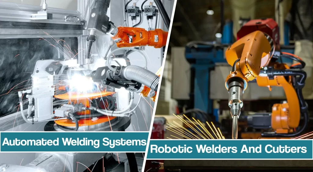
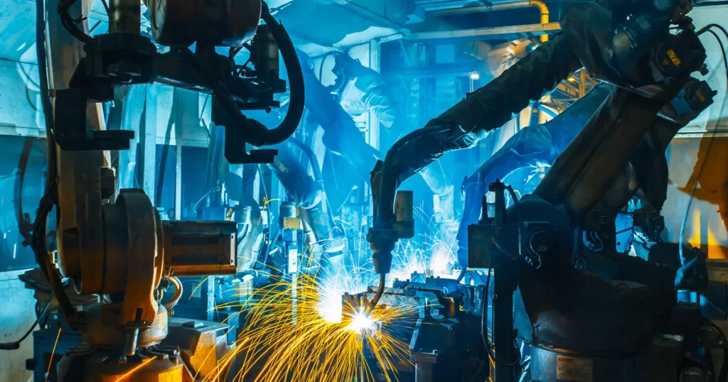
Sooner or later, your manufacturing business might grow and you’ll be in a need of welding automation products. Welding automation includes robots for cutting and welding, which can vary on your needs.
This article will discuss automated welding systems and robotic welding automation technology and its benefits.
Even though initial investments in automation products can be high, increased productivity and high welding speed systems can pay off the investment quickly. However, you will have to ask yourself is it worth.
Robots to cut and weld
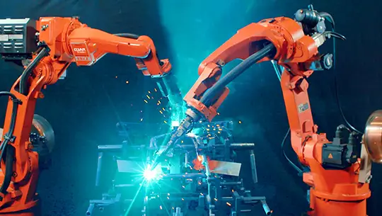
Robots for cutting and welding generally operate with five or six axes of motion. They are machines operated by motion controllers, sometimes connected to process controllers that direct and monitor cutting and welding procedures.
Preferred for optimizing productivity and weld quality control are robot controllers that control the cutting or welding process.
Selecting a robot and automated welding system, the engineer should consider several different factors. Here are some of the most common ones.
- Positional repeatability: The ability of a robot to return to a programmed position. Listed as a plus-or-minus value, this value rates the rigidity of the entire robot system.
- Load capacity: the weight the robot arm can carry, usually rated at full arm extension and maximum acceleration.
- Power: electric robots use servo motors. The position is controlled with feedback from encoders mounted on the ends of the motors
However, you shouldn’t disregard the factors we will cover next.
Work Envelope
The volume can be reached by the end of the robot arm. Manufacturers normally base the work-envelope size on the P point, where the wrist bends.
However, when evaluating the work-envelope size, remember that the length of the welding gun or torch can extend or detract from the reach depending on torch angles.
For cutting and welding, consider what torch angles will be required on welds locations near the outside limits of the rated work-envelope volume.
Welding and Cutting Speed
Cutting and arc-welding robots need to move at a wide range of speeds, fast between cuts or welds, and slower while cutting or welding. Resistance-spot-welding robots require high speed with controlled acceleration and deceleration to smooth the movement of the arm.
Manufacturers rate robot speed in degrees of axis motion per second-typically, main axes move on the order of 100°/s, while wrist axes index at up to 300°/s on medium-sized robots and 200°/s on heavy-duty models.
Welding often involves multiple torch angles so faster wrist speeds may have a larger effect on reducing cycle time and lower costs. Another way to compare robot speeds is total the speeds of all axes to get a composite speed for all 6 axes.
Robotic Positioners
Robot productivity can often be increased by using positioners to orient the part in front of the robot. Positioners can provide either indexing motion or servo-controlled motion. Indexing positioners move between two or more fixed positions and are normally sequenced by outputs from the robot controller.
Positioners can be equipped with the same servo motors that drive the robot and are controlled like robot axes. Most controllers provide the ability to perform “coordinated motion” with the robot.
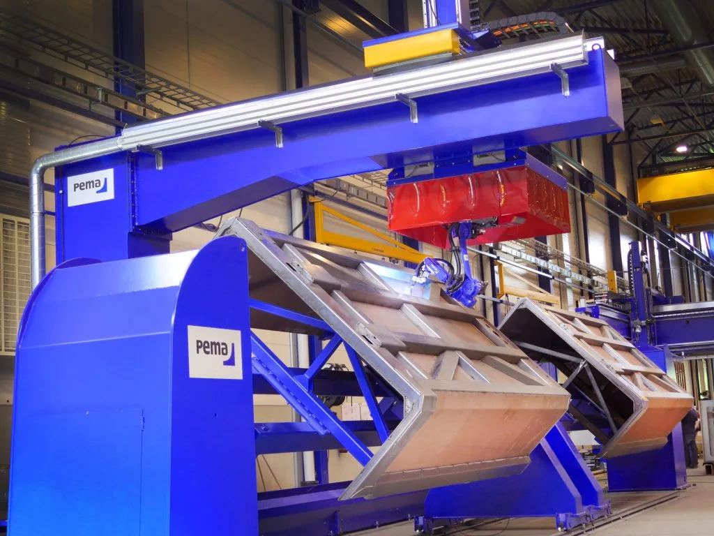
This allows a circumferential weld to be made while the part turns on the positioner. The robot can move and change angles as the part turns to weld irregular shapes or parts that are offset from the centerline of rotation.
Motion Control for Welding And Material Handling
Typically, the torch is mounted on the end of the arm and it is positioned around the part. Some application flexibility can be obtained by using the robot to grip the part and move it to a fixed torch. With this approach, the robot can do multiple operations like adding spot welds or project weld nuts in addition to conveying the part.
Some robot controls provide the ability to control multiple robots at the same time. This can provide increased productivity by placing multiple arc welding robots into a workcell. This capability can also provide application flexibility by combining material handling robots to position parts for processing by arc welding robots.
Robotic Fixturing
In most cases, a fabricator needs custom-designed and built fixtures to hold the parts in place for robotic welding. Fixtures must hold the same tolerances as those required of part dimensions while allowing for easy loading and unloading.
Fixtures for robotic welding must hold weld joint locations consistently (about ± half the wire diameter). This is a design criterion that is not normally associated with fixturing for manual welding. Some fixtures may require automatic clamping controlled by the robot controller and back-gas purging and heat-sinking properties. Fixtures with a high degree of automated clamping often use their own PLC controllers, although robot controllers are continuing to expand in their ability to control other cell devices.
Operator and Robotic Safety
Worker protection calls for safeguards to keep personnel away from the moving machine and provide protection from arc radiation. Light-beam barriers and sensors in floor mats cut power to the robot and positioner when personnel enters the robot cell or work envelope. The ANSI/RIA R15.06 specification covers the safeguarding of robotic systems.
Arc welding Automated welding system
Most arc-welding robots and automated welding systems use off-the-shelf MIG welding equipment.
Look for the original equipment manufacturer rated at the appropriate current level and duty cycle for the application that uses closed-loop control, where the wire feeder and the power supply accept feedback signals so the circuit can maintain programmed parameters.
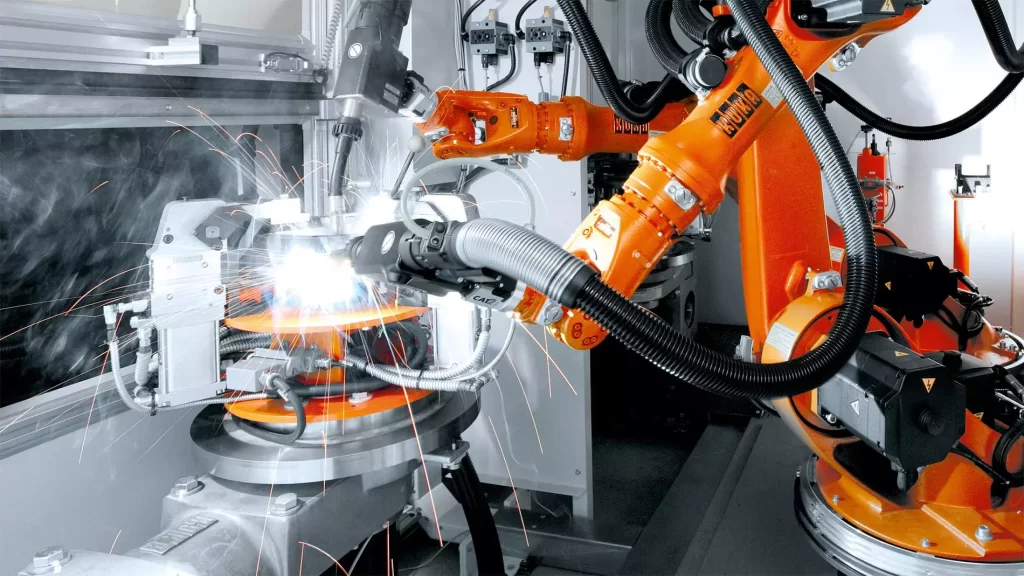
Welding manufacturers often provide automation automated welding process versions of their power sources with some type of interface to accept control signals from a remote source. Robot manufacturers provide “interface” schemes to control the welding equipment. Be sure there is a well-thought-out interface scheme between the robot and the power source you are considering.
Power Supplies
Solid-state power sources with high-speed output switching are preferred for better arc characteristics and cost savings.
Multi-schedule power supplies allow users to program several welding schedules and permit switching between schedules as the robot control demands. With a digital-analog control interface, the robot controller can vary welding power continuously.
The MIG Welding Gun In Robotic Welding
GMAW torch should be hefty enough to withstand the high-duty cycles of robotic welding. Given the high arc-on time of robotic arc welding, users should consider water cooling for the weld gun.
Some installations require a wire straightener to maintain the arc position at the end of the welding wire. Guns require a torch-to-robot-tool-face attachment bracket to align the axis of the gun with the axis of the gun-mount flange.
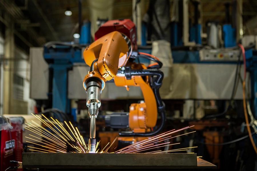
Breakaway torch mounts avoid damage from the collision. An alignment fixture helps to calibrate torch position, keeping position constant relative to programmed points.
Robot Wire Feeder
Select automation products that deliver high torque and quick response. Four-roll feed heads are most commonly used—Mount the feeder on the robot arm to minimize wire-pull distance. Bulk wire packages are commonly used with robotics. This requires a flexible conduit to be run several feet from the wire location to the back of the feeder. Wire delivery may be enhanced by using powered de-reeler equipment or assist feeders, depending on the feed distance.
Robot “Dress” for Welding and Cutting. Robots are highly flexible and have a wide range of motion. Continued cable flexing and exposure to molten sparks can lead to premature failure and downtime. Look for “dress” packages that have the cabling neatly routed and protected from spatter. Cables and hoses should have strain relief, a wide flexing radius, and be located away from surfaces that can rub.
Optional Equipment
Devices like nozzle cleaners are sold as optional equipment and can improve the uptime of the robotic work cell. Seam tracking devices, torch alignment devices, arc monitoring devices, etc. are equipment options that expand the effectiveness of robotics for different applications.
Boom-Mast assemblies
These comprise a vertical mast and a horizontal boom that carries the welding head. Specify them with two dimensions—maximum height from floor to arc, and reach of the arc from the mast. A typical range of this equipment, specified as boom and column stroke, is 4 by 4 to 14 by 14 ft, but larger setups are available. To extend the work envelope of the assembly, mount it on a carriage that rides on rails anchored to the shop floor. On some heavy-duty models, an operator sits on a seat attached to the end of the boom with the weld-wire supply and a control station.
To select and specify a boom-mast setup, fabricators must determine the weight to be carried at the end of the boom, and allowable boom deflection. The welding torch should move smoothly at weld-travel speeds.
Robotic Welding carriages and tractors
- Side-beam carriages perform straight-line longitudinal welds. Typically, the weld head mounts on a carriage that rides an I-beam fitted with equipment to enable powered carriage travel. The carriage conveys the weld head, wire supply, operator controls, and flux (for submerged-arc welding). Weld-head position adjusts up and down, in and out. Carriage travel speed adjusts, typically between 5 and 200 in./min; for maximum productivity, specify a unit with rapid return speed.
- All-position carriages employ a special track that enables mechanized vertical-and horizontal-position welding. The track is supplied in either a flexible or formed version to fit a range of diameters. It attaches to the workpiece with magnets or suction cups. Applications include horizontal girth welding on storage tanks; vertical welding on joints of ships; and welding inside aircraft assemblies with a carriage known as a skate welder capable of following irregular joint contours.
Welding Tractors In Welding Automation
Welding tractors are an inexpensive way of mechanizing weld-head motion, ride on the material being welded or on special tracks. They are found in shipyards and in plate-fabricating shops to make long, straight welds. Special designs include two-weld-head models that can straddle, and weld from both sides, such as a stiffener to a plate.
Also available to fabricators are standardized automatic arc-welding machines, designed for welding certain types of products.
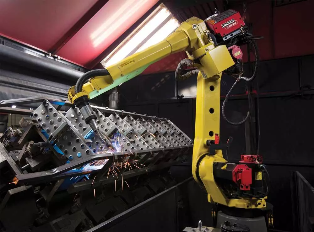
The most common of these is the seamer, a beam-and-carriage machine that welds the internal or external seams of tank shells. Machine design can call for a cantilevered beam or a fully supported beam.
Most external seamers are cantilevered to enable the tank shell to hang below the beam and the carriage to traverse over the top of the longitudinal shell joint with the weld joint at 12 o’-clock. Using a cantilevered machine allows easy loading and unloading of cylinders and other closed sections. Using an internal seamer, the operator slides the rolled shell over the beam at one end of the machine, with the carriage-riding torch inside the cylinder and the weld joint at 6 o’clock. Manufacturers of these machines will include a copper heat-sink backup bar with a machined backup groove to customer spec, as well as a water-cooled mandrel.
External seamers are designed to make 100%-penetration single-pass welds on untacked cylinders and flat sheets without distortion to the workpiece. Generally, external seamers come in standard lengths from 2 to 16 ft., and internal seamers from 10 to 25 ft., although specially engineered machines have been made for weld lengths of 55 ft. or more.
Resistance Welding Robots
Robots for resistance welding generally require six degrees of motion-three for robot action and three at the robot wrist to position the welding electrodes perpendicular to the plane of the sheet metal to be welded. The work may move on a positioner or a continuous rail, typical in the automotive industry, allowing greater freedom of movement but demanding more coordination capability from the controller.
Resistance Welding Gun
Guns can be actuated by air, hydraulic, or eclectic power. A recent advancement includes using servo motors for gun actuation. This allows the robot controller to provide a consistent clamping force at the electrodes. Important properties of the robotic RSW gun: weight, the distance between its center of gravity and the tool-mount face, and its mass and moment of inertia.
The moment of inertia increases as the square of the distance of the gun center from the robot-wrist flange.
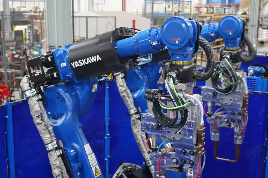
This limits the dynamic movement of the robot, since restraints on acceleration and deceleration limit production rates. Robot guns should be self-equalizing, floating when the electrodes clamp so that reaction forces are not transmitted to the robot arm.
Controls for RSM Robots
Resistance welding generally uses controllers that are independent of the robot control to carry out clamping, welding, holding, and release of electrodes. Most software allows for the selection of different welding schedules from the weld-process controller. Some manufacturers have integrated controls to the point where they can be programmed from the robot teach pendant.
Controls for spot welding are either AC (which uses SCRs) or DC (which uses mid-frequency inverters). The type of power used will affect transformer selection.
Overhead Transformer
This arrangement has the welding gun swivel-mounted to the robot wrist with the transformer mounted on a rail suspended above the robot so as to follow the movement of the wrist without excessive drag on the cables.
The cables that connect the transformer to the gun are long enough to allow free movement of the robot; extra length, however, increases the impedance. Cables should be as short as practicable and cross-sectional area smallest possible without causing overheating.
Robot-mounted Transformer
This arrangement has the transformer mounted on the robot arm or inside the robot housing. The idea is to place the transformer as close as possible to the gun, minimizing weld-cable length.
Gun-transformer Unit (Transgun)
Many RSM applications use an integral gun-transformer unit. These can often be too heavy for manual use, but, properly designed, suitable for robots. They eliminate the need for secondary cables, using only small flexible primary cables. Impedance is present only at the gap of the electrodes, so the transformer is small. The unit attaches to the face of the robot’s wrist with its center of gravity as close to the face as possible. Specify them with two dimensions.
Automated Orbital Welders
Orbital welding automation is performed on tubing and pipe. The weld head rotates around the joint; a remote control pendant or head-mounted controls direct travel speed. Units weld tubes from 1 /4- to 8-in. o.d. and larger, with wall thickness from 0.015 to 1 /2 in. A standard automated orbital-welding setup includes the welding head and a device that attaches to the pipe or tube to move the head around the joint.
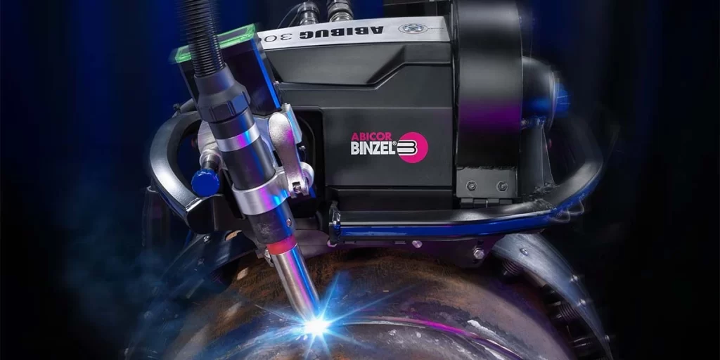
Also included are a power supply and wire feeder for GMAW and non-autogenous GTAW, a programmable controller, which may be integrated into the power supply, and a cable for delivery of power, shielding gas coolant. Most systems for joining thin-wall tube come with water-cooled heads to minimize heat input. An option, practically a necessity, is a remote-control pendant to allow an operator to follow welding action closely at the joint and to modify the welding current in the process.
For welds in critical thin-wall tubing, fabricators select a fixed-head device. It performs autogenous welding, turning the tungsten-electrode-holder assembly, driven by a small DC gear-motor, within the head around the tube joint. The head body straddles the weld joint and remains stationary.
The enclosed chamber is flooded with shielding gas; the arc length remains fixed. This design encloses the welding head entirely within the housing, which bridges the weld joint. Head housings are of fixed size, but some can accommodate a limited range of tube sizes by use of adapter inserts. They weld tubes 1 /2-in. wall thickness. Special heads will weld tubes as small as 1 /8-in. diameter.
In-place Limited-function Heads
These carry an adjustable lever-actuated clamp to hold the head to the workpiece, allowing its use on a limited range of workpiece o.d. The clamp, a split-ring or chain-drive assembly, acts as a track around which the welding torch, centered over the joint, rotates. The torch and wire feeder are mounted on a rotating disc; a torch-cable assembly delivers weld current, cooling water, and shielding gas to the weld head. A mechanical follower device, using the workpiece surface as a reference, corrects arc-length changes due to any out-of-roundness in the work. This type of head enables the use of filler-wire feeders.
- Full-function in-place heads can include electronic arc-voltage control and torch oscillation, useful for depositing multipass welds on pressure pipe. They install quickly, clamped to one side of the joint. However, each head can weld only a finite range of workpiece sizes, and heads are not water-cooled, limiting their use on alloys requiring preheat.
- Full-function orbital heads get the call for large-diameter pipe, 8-inch diameter, and larger. A welding carriage runs around the pipe joint on a circumferentially mounted track or guide ring clamped onto the pipe o.d. These come in a hinged clamshell design, useful for pipe to 10 inches in diameter, or as a long flexible track that can be maneuvered over the pipe and clamped end to end. The most useful designs allow easy changeout of the torch head on the carriage, for applications like root-pass welding by GTAW followed by fill-pass GMA welding. Such heads typically require constant-current and constant-voltage power, necessitating the use of two power supplies or a single multi-process unit. They incorporate electronic arc-voltage control and torch oscillation. A typical high-capacity unit 4-in. diameter and larger welds wall thicknesses to 2 in., oscillates at 0.4 to 20 in./min, moves the travel carriage at up to 13 in./min, and can feed the welding wire at up to 150 in./min.
Guide rings come in standard pipe sizes (ASTM A106, Standard Specification for Seamless Carbon Steel Pipe for High-Temperature Service), designed to account for the tolerances encompassed in the ASTM standard.
The carriage should provide for manual x, y, and z adjustment of the welding head, as well as torch-tilt for lead or lag angle. Other adjustments may include voltage control (z-direction movement) and cross-joint oscillation.
Wire feed for smaller orbital setups usually comes from a small spool4 ounces is a common maximum size. A wire straightener is helpful, considering the tight cast of filler wire wound on the spools. Large-pipe welding units, of heftier construction, feed wire from carriage-mounted reels.
Power Supplies For Automated Orbital Welding
Power supplies tend to be at the top of the range, with a high level of micro-computer control of pulsing parameters and multi-schedule welding parameters. Fabricators should select them to rate at a 100-percent-duty cycle for the welding current operation.
Microprocessor-based units typically can store up to 100 weld programs— the operator merely calls up the appropriate weld schedule and pushes a button.
Programs allow changes to welding parameters as a function of weld-head rotational position. These power supplies also feature automatic weld-procedure generation, allowing the operator to enter basic parameters such as tube diameter, wall thickness, and weld-travel speed.
The program then automatically creates a near-perfect weld procedure, simplifying the weld-development process, with only one or two test welds required to fine-tune the program.
The Automation process controller
The process controller may control torch travel, torch oscillation including side dwell, arc-gap length, welding current, shielding-gas flow including pre-and post-weld purge, high-frequency start for GTAW, torch descent and retract for touch starting, and wire-feed speed. It may synchronize a group of actions, such as current pulse, wire feed, oscillation dwell, and carriage travel.
Some units synchronize oscillation dwell time with an extra current pulse to ensure good side-wall fusion. The controller can also carry software that automatically selects the appropriate tube-welding head based on the application. Then, after the operator selects the desired tungsten speed, the software calculates the correct RPM setting for the selected weld head.
Controlling pipe welding, microprocessor-based controls allow programming a multipass weld with specific procedures for each pass from root to cap with an uninterrupted weld, eliminating mistakes in setting parameters. The operator can program changes in parameters during each pass around the pipe.


