All too often, engineers assume something must be true without analyzing the underlying principles involved.
Deep down in their hearts, they intuitively “know” something to be accurate, and when this is the case, they are unlikely to question the assumption. After all, it is “obvious” and “true.” That is what I call “designing with your heart.”
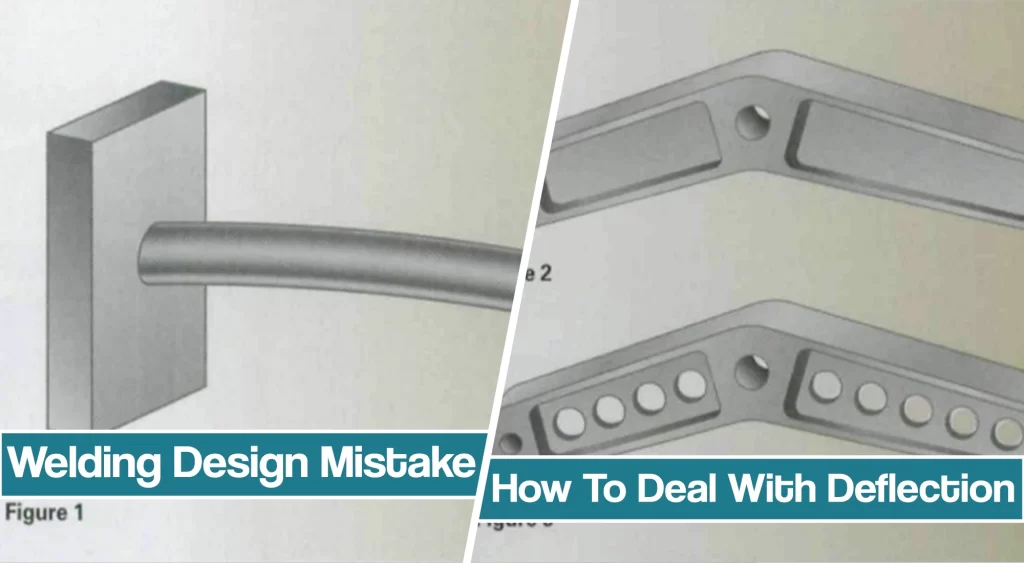
As a way of thinking about this kind of situation, let’s consider a welding design mistake, a hypothetical example: the cantilevered tubular assembly shown in Figure 1.
Common Welding Design Issue – Deflection
To keep things simple, we will state that the only forces involved were those resulting from the tube’s weight.
The initial assembly was made of low-strength, mild steel. When completed, the assembly deflected excessively. A seemingly obvious solution might be to make an identical replacement but fabricate it from high-strength, low alloy steel.
However, if we were to do this, we would find that the deflection is similar.
Why? Because the material property that governs deflection is the modulus of elasticity (E), and it is the same for all steels, regardless of strength.
Addressing The Issue in The Weld Design
Since the weight of the tube is causing the deflection, we might decide to try again, this time making the assembly out of the higher strength steel but with a thinner wall thickness. We are assuming that the decrease in thickness will reduce the weight and accordingly reduce the deflection. Alas, we will find that the results, again, are essentially the same.
Why? Because the resistance to deflection is governed by the properties of the cross-section, the moment of inertia (I), which for the circular tube decreases simultaneously and proportionally to the reduction in the wall thickness.
Some simple engineering equations and mathematics could have helped us to cut through all the emotion with cold, hard facts. We could have predicted the deflection of the tubular assembly before anything was built by applying the following equation:
w = the weight per length of the tubular steel L = length of the tube
E = modulus of elasticity of steel
(i.e., 30×106 psi)
I = moment of inertia.
The moment of inertia (I) for a circular section for which the wall thickness is small can be found from the following:
I = tpr3
where
t = the thickness of the tube wall
r = the radius of the tube.
Finally, to get the weight per length of the tube, the following relationship can be used:
w = 2prtd
where
d = density of steel.
Results of the Calculation
Combining these relationships, one obtains the following:
This simple calculation shows why all three approaches would have had the same deflection (D). With the density (d), length (L), and modulus (E) all fixed, the only variable remaining is the tube radius (r). Thus, the only way to limit the deflection is to increase the diameter of the tube (i.e., expand the radius “r”). Fortunately, since this term is squared, a slight increase in the radius will significantly reduce the deflection.
Our hearts may tell us otherwise, but the cold hard mathematical facts reveal the truth — a truth that could — and should — be known before anything is fabricated.
Real-Life Example Of Welding Design Mistake
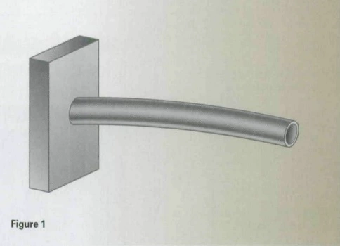
Now, for a real-life case example. Many years ago, when I was selling for Lincoln Electric, I called on a company that made machines that used to pack salmon into cans. The machine operated at high speed and incorporated a pivoting lever that was made of cast steel (see Figure 2).
Unfortunately, when the machine was operating, the lever was subject to high forces of inertia that caused the device to bind. Slowing the operating speed of the machine eliminated the binding but hampered production.
So on the day I arrived, the designer was modifying the pattern for the cast steel part to permit the lever to be made of lighter aluminum instead.
When I asked the engineer to explain the intent behind the change in material, he explained that the machine was binding because the lever was deflecting excessively due to inertia forces. Those forces were due to the rapid deceleration of the lever, and he believed that reducing the mass of the lever would cause the forces to be reduced.
Since F = ma, and since the density of aluminum is approximately one-third that of steel, the mass (m) would be decreased, and the force (F) would also be reduced to about one-third of what was experienced with the steel lever. In his heart, the engineer knew this would solve the binding problem. Or, as I would say, the engineer was “madly in love with the low density of aluminum.”
Unfortunately, he had failed to recognize that another material property was also being changed with the change to aluminum, namely the modulus of elasticity (E). As we showed in the example of the cantilevered beam, the modulus of elasticity stiffens a member. So while the driving force would be reduced with an aluminum lever, the resistance to the force would be proportionately reduced as well. The change from cast steel to aluminum would produce no benefit. Again, engineering equations and mathematics provided the cold, hard facts to challenge one’s heart.
Calculation That Solved the Issue in Weld Design
If the load caused by inertia is estimated to increase linearly from zero at the pivot to a maximum value at the end, and if L represents the half-length of the lever (i.e., the distance from the pivot to the pinned end), then the deflection of the lever can be estimated from the following relationship:
where W is the total inertial force. Since W = (fL)/2, and f = mA (where A is the cross-sectional area of the lever), then the following estimate of deflection due to deceleration is obtained:
Since acceleration (a) and the length (L) are fixed, then the deflection is proportional to the cross-sectional area (A) and the density (d) and inversely proportional to the modulus of elasticity (E) and the moment of inertia (I). Two of these are related to the section (A and I), and two are material related (d and E). Therefore, to reduce deflection due to inertial loads, either d/E or A/I or both must be reduced.
| Material | Density(b) (lbs/in3) | Modulus Of Elasticity (E)(psi) | Ratio Of Density To Modulus (b/E) | Ratio of b/E compared to steel |
|---|---|---|---|---|
| Steel | 0.283 | 29 (10^6) | 0.976 (10^-8) | 1.00 |
| Aluminum | 0.0975 | 10.3 (10^6) | 0.947 (10^-8) | 0.97 |
| Magnesium | 0.0628 | 6.5 (10^6) | 0.966 (10^-8) | 0.99 |
Table 1 summarizes the material properties, comparing the original cast steel lever to the proposed aluminum lever. Magnesium has been added for comparison. The table shows that d/E is essentially the same for all three materials. Thus, a material change would not help.
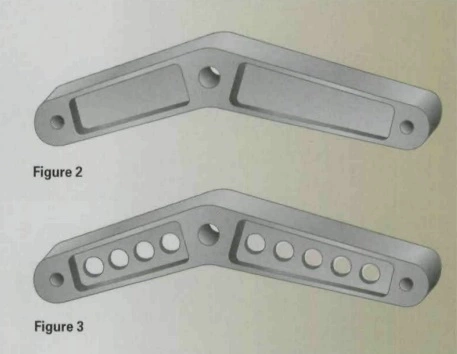
The only way to reduce the deflection of the lever was to reduce A/I, or using the inverse, to maximize I/A. The challenge, therefore, was to minimize A more than I was deflated. As shown in Figure 3, holes were created in the lever, reducing the cross-sectional area A more than the moment of inertia I was reduced.
So the moral of our story is: “Don’t design with your heart.”


