Welding shops require many types of equipment, including power supplies, guns, torches, wire feeders, flux-handling devices, accessories such as cables and ground clamps, and consumables—filler metals, fluxes, and shielding gases.
For brazing, shops employ furnaces and custom-built fixtures.
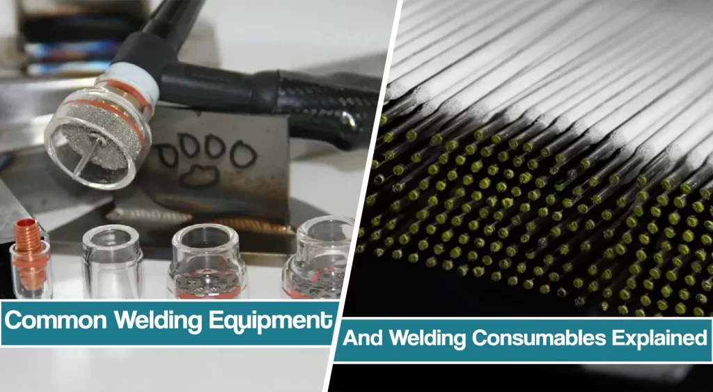
This article will discuss standard welding equipment and consumables, and their role in different welding processes such as TIG welding, MIG welding, Stick welding, Gas (Oxyfuel) welding, and brazing.
Shielded Metal Arc ( SMAW, STICK ) Welding Welding Equipment And Consumables
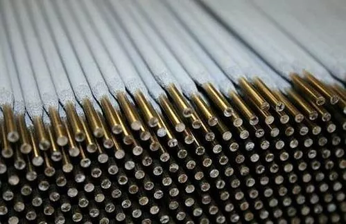
AWS (American Welding Society) A5 specifications set standards for electrodes for SMAW of carbon, stainless, and low-alloy steels; aluminum, copper, and nickel and their alloys; and weld-surfacing. Designations for covered electrodes carry the prefix ‘E’. Packaged to AWS specifications, electrodes come in boxes, cans, or other containers, labeled with their AWS specification and trade name, quality-control (heat or lot) number, supplier name, diameter and length, and weight of contents.
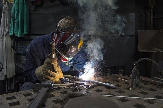
Specifications require that every electrode be marked for identification near its numeric designation at the grip end. To select a covered SMAW electrode, consider these factors in approximate order of importance.
- Mechanical properties of the base material. The tensile strength and yield strength of the weld metal should equal or exceed that of the base material. Ductility and toughness at low temperatures may also be necessary. High-temperature service requires resistance to creep. Shock loading requires impact resistance. In general, weld metal should exceed base-material properties.
- Composition of the base material. Chemical composition is essential for stainless steels, low-alloy steels, nickel and copper alloys, and materials that serve in corrosive atmospheres. Consider the possibility of electrochemical corrosion between base and weld metal of different compositions.
- Welding position. The first performance characteristic to consider. High-cellulose coatings, like those on E6010 and E6011 electrodes, generate a light slag that makes for rapid solidifying of the weld metal, suitable for out-of-position welds. Also good are rutile-fluxed electrodes-E6012 and E6013that hold out-of-position weld metal in the place as it solidifies.
- Welding current. Covered electrodes run on AC, DC, or both. When welding DC, the positive lead typically connects to the electrode (DCEP, or reverse polarity). Some suppliers design electrodes that weld with the electrode negative (DCEN, or straight polarity). Assure the electrode will perform with the available current.
- Joint design and material thickness. Some electrodes create an arc that penetrates deeply, performing well on thick sections with narrow grooves or no bevel. Poor fit-up calls for electrodes that can bridge wide gaps.
- Efficiency. Meeting all other conditions, engineers select the electrode that gives the highest deposition rate. For heavy-section joints, use powder-metal-addition fillers.
Stick Welding Electrodes
Designating electrodes for carbon and low-alloy steels, following the prefix ‘E’, to signify a SMAW electrode, come two or three digits to indicate minimum tensile strength in 1,000 PSI units; a digit indicating usable current and electrode-coating type; and, in some cases, a hyphen followed by a letter and number suffix to denote weld-metal composition. Example: E7010-A1 is a SMAW electrode (E), of the 70,000-PSI tensile strength (70), for use in all welding positions (1), having a high-cellulose-sodium coating for use with DCEP (0).
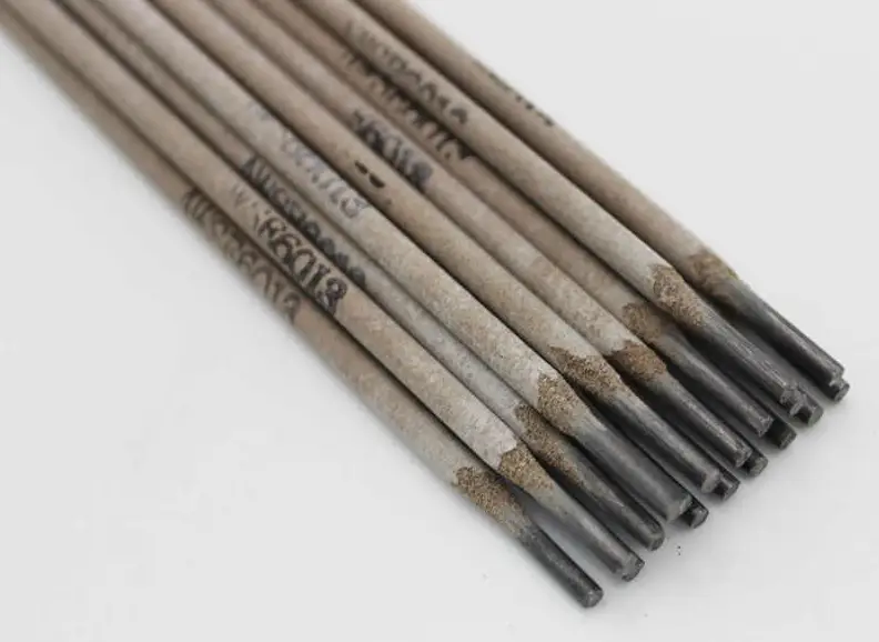
A1 indicates a particular composition listed in the A5 specification. A -1 suffix, as in 7018-1, indicates high impact toughness at a temperature lower than specified for a standard E7018 electrode.
Low-hydrogen types
These basic-coated electrodes, EXX15, EXX16, EXX18, EXX28, and EXX48, are formulated with low-moisture-retaining coatings and manufactured to contain low levels of hydrogen. Hydrogen-controlled electrodes minimize the risk of hydrogen-induced cold cracking when welding high-tensile steels on restrained structures. Fabricators use these electrodes to reduce or avoid the need for pre-or post-weld heat treatment to drive hydrogen from weld metal.
Weld metal diffusible hydrogen content varies from 1 to 16 ml/100 g. Optional designators H16, H8, and H4 set decreasing limits on hydrogen content in the deposited weld metal. An optional electrode designator, ‘R’, indicates an electrode that is moisture resistant; it will not absorb water in excess of a specified limit after exposure to humidity. Low-hydrogen electrodes should be used in dry conditions and may require baking after exposure to the atmosphere.
High-deposition electrodes
These contain iron-powder additions in the coating to raise the deposition rate. Designations: EXXX4, EXXX7, EXXX8.
For the fastest deposition, use the largest diameter possible for an application the thicker the electrode, the greater its current-carrying capacity and the higher the deposition rate. Welding out of position and over-head, select a small-diameter electrode to enable welders to reach into narrow root openings.
Gas Metal Arc (GMAW, MIG) Welding Equipment
GMAW typically uses solid wire, spooled or reeled, for continuous feeding to the gun; diameter, 0.030 to 1 /16 in. typically, although wires as small as 0.020 in. and as large as 1 /8 in. are sometimes used. AWS lists specifications for filler wires of copper and its alloys, aluminum and its alloys, surfacing alloys, nickel and its alloys, titanium and its alloys, carbon and low-alloy steels, magnesium alloys, stainless steel, and zirconium and its alloys.
MIG Welding Wires
For special applications, manufacturers offer metal-cored wires for GMAW. These are composite electrodes comprised of a metal sheath with a powder-metal core. They are often confused with flux-cored wires, which form a slag that completely covers the weld-bead face; metal-cored wires produce minimal slag.
A significant advantage of metal-cored wires is the ability to manufacture specialized-alloy compositions not easily available or producible in solid-wire form. Modifying the composition of the powder-alloy core allows the wire manufacturer to customize wire formulations to metallurgical, compositional, or physical properties per customer demand. Horizontal-fillet welds made with metal-cored GMAW can deposit weld metal at rates up to 20 percent higher than with solid wire.
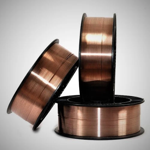
Alloying elements, such as silicon, in the powder-metal core improve sidewall wetting and reduce weld-bead convexity by reducing surface tension of the molten weld pool. For this reason, flat and horizontal welds deposited with metal-cored wires have a better appearance than weld metal deposited with flux-cored and solid wires. Compared to solid wires, metal-cored wires also result in higher current density, for increased penetration; a wider operating window with respect to welding-process variables; better sidewall melting; and less lack of fusion.
Flux-Cored-Arc Welding Equipment and Consumables ( FCAW )
This process is a variation of GMAW. Electrodes comprise a metal sheath surrounding a core of fluxing and alloying compounds. Self-shielded (FCAW-SS), it uses gas generated by breakdown of a powder-flux core inside the wire to shield the weld. Gas shielded (FCAW-GS), external gas supplies shielding.
The compounds in the electrode perform essentially the same functions as the coating of a covered electrode used in SMAW:
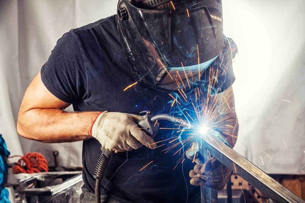
To form a floating slag coating on the weld pool to protect the weld as it solidifies; deliver deoxidizer and scavengers to help purify the weld; deliver arc stabilizers to minimize spatter; add alloying elements to the weld, for optimum mechanical properties; and provide shielding gas.
Flux-cored electrodes
Filler-metal selection for FCAW depends on base-metal composition, cleanliness of base metal, thickness, and service. AWS specifications: A5.20, Specification for Carbon Steel Electrodes for Flux-cored Arc Welding, for low-carbon steel up to 0.15 C and mild steel 0.15 to 0.29 C; A5.29, Specification for Low Alloy Steel Electrodes for Flux-cored Arc Welding, for steel of higher carbon content and the low-alloy types; A5.22, Specification for Flux-cored Corrosion-Resisting Chromium and Chromium-Nickel Steel Electrodes, for stainless steels.
Gas Tungsten Arc (GTAW, TIG) Welding Electrodes
GTAW uses an arc between a non-consumable electrode and the work. It joins with or without filler metal. AWS A5.12 lists electrode types and sizes. All are tungsten, some with thoria, zirconia, ceria, or lanthana added.
Thoria provides higher current-carrying capacity than pure tungsten with less contamination of the weld pool. Other benefits: better arc starting, greater arc stability.
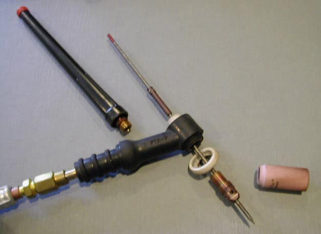
Zirconiated electrodes perform well with alternating current: the arc is stable, the electrode retains a balled end during welding, and has a current-carrying capacity of thoriated electrodes. In addition, zirconiated electrodes resist contamination and minimize tungsten contamination of weld metal.
Electrodes come 3 to 24 in. long, 0.01- to 0.25-in. diameter. Colored markings—bands or dots—indicate composition: pure tungsten, green; 1-percent thoriated, yellow; 2-percent thoriated, red; ceriated, orange; lanthanted, black.
TIG Weleding Filler metal
GTAW does not usually require the addition of filler metal, but filler is commonly added when base-metal thickness is greater than 1 /8 in. Filler metal for carbon steel are described in A5.18, and for low-alloy steels in A5.28.
Submerged-Arc Welding Equipment and Consumables
SAW Welding Flux
AWS specifications A5.17 and A5.23 describe fluxes for SAW. AWS designation of fluxes precedes that of the wire when identifying a combination for a welding procedure. For example, the designation F7A2-EM12K indicates a flux (F) that will provide, with a given wire designation, tensile strength of 70,000 PSI (7), in the as-welded condition (A), and impact properties of 20 ft-lb at -20 F (2). A designation containing a P rather indicates the flux properties after post-weld heat treatment.
- Fused fluxes are melted in a furnace, chilled, then crushed and screened for size. They recycle without alterations in particle size or composition.
- Bonded fluxes are powdered materials mixed dry and bonded together with a silicate, pelletized, baked, broken up, and screened for size: the process permits easy addition of deoxidizers and alloying elements. Bonded fluxes allow thicker flux layers when welding. Disadvantages of bonded fluxes are their absorption of moisture and alterations during handling in particle size and composition due to particle segregation.
- Agglomerated fluxes are similar to bonded fluxes except that they use a ceramic binder. They require higher baking temperatures during manufacture.
- Mechanically mixed fluxes are combinations of two or more bonded or agglomerated fluxes. They allow special flux mixtures for critical welds, but they may separate during storage, use, and flux recovery.
Three-part new flux mixed with one-part recovered flux works well. Consult the flux manufacturer for proper proportions.
Fluxes classify as basic, acid, or neutral. Fluxes that contain oxides and break up easily during welding are basic. These provide oxidizing action and alloy with the weld metal to obtain desired mechanical properties. Acidic oxides break up slightly, for the same reasons. Welding voltage must remain within the range specified by the manufacturer of acidic and basic fluxes. Excessive arc voltage increases the alloying of flux constituents with the weld metal. Neutral fluxes do not oxidize alloying elements or add alloying elements to the weld. As amperages increase, flux-particle size should decrease. Excessive current for a particle size produces unstable arcs and uneven weld bead edges.
SAW Weld Wire
SAW uses electrodes of continuous wire, solid or flux-or metal-cored. Selection depends on base-metal composition and thickness, flux, joint design, and cleanliness. AWS specifications A5. 17 and A5.23 detail filler materials for SAW of carbon and low-alloy steels; A5.9 and A5.14, filler metals weld corrosion-resisting stainless steels and nickel alloys, respectively.
Hardfacing Consumables Electrodes
Hardfacing welds a wear-resistant material to a substrate-base material that is commonly mild, alloy, or stainless steel.
Hardfacings can be deposited manually using SMAW electrodes; semiautomaticaly using solid wire and self-shielded flux-cored electrodes; or automatically by submerged-arc welding. The method chosen depends on the size and accessibility of the area to be surfaced.
Select hardfacing materials based on weld-deposit microstructure and the wear situation the part will encounter, with consideration given to thermal treatments applied to the material before and after hardfacing. Deposit chemistry can be crucial in attaining the desired corrosion resistance or wear properties, or for minimizing the risk of solidification cracking.
Acceptable deposit chemistry is achieved through the initial choice of consumables, using wire analysis and flux composition, and by specifying the number of weld passes needed to reduce parent-metal dilution to within acceptable limits. With the submerged-arc process, the flux and electrode govern the characteristics of the applied hardfacing. For example, those fluxes neutral to manganese and silicon are not necessarily neutral to carbon and chromium, elements that matter most in hardfacing.
Hardfacing Alloys
Hardfacing alloys contain as base elements typically iron, nickel, or cobalt, to which metallurgists add varying amounts of carbon, chromium, molybdenum, tungsten, silicon, manganese, vanadium, and boron. To raise hardness, the primary property for wear resistance, alloy designers add elements that either form hard constituents (carbides, borides, or Laves phase), or that strengthen the matrix by going into a solid solution.
Carbon content determines toughness and abrasion resistance—as carbon rises, abrasion resistance increases and toughness drops. Chromium forms carbides, increases corrosion resistance, and adds high-temperature strength. Tungsten, a potent carbide former, also boosts high-temperature strength, as does cobalt. Tougheners include nickel and manganese. Boron forms hard wear-resistance borides.
- Iron-base alloys, the most widely used hardfacing materials, combine versatility with moderate cost. They achieve wear resistance by forming carbides and martensite, a hard matrix structure that forms on quenching and toughens with tempering. Pearlitic alloys, usually containing less than 0.30 percent carbon, are comparatively soft and ductile.
- Nickel-base alloys resist corrosion and heat better than iron-base alloys. They come in three types, depending on the hard phase (boride, carbide, or Laves) that forms on cooling. In boride-containing alloys, large amounts of chromium borides provide wear resistance.
- Cobalt-base alloys provide more high-temperature corrosion resistance than iron-base and nickel-base grades. In addition, carbides or Laves-phase give wear resistance.
Welding Cables and Accessories
Cables, large-diameter sheathed wires, conduct electricity, linking power sources to work, and electrode holders. The current passes through lugs, connectors, and splices along its route. Welding cable generally has drawn annealed strands of copper, 30 or 34 AWG (American Wire Gage). Though 30-gage cable is more common, choose the finer 34-gage wire if you need maximum flexibility.
When specifying cables, remember to distinguish between ground and work cables. The work lead carries current from the power source to work; the ground lead carries current to the ground, from which it completes the circuit to the source.
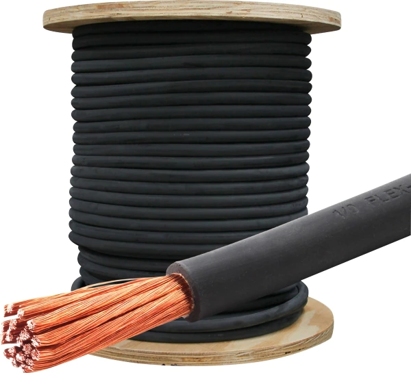
Some cable is of aluminum wire, lighter and less costly than copper. Specifiers prefer aluminum cable for low-duty-cycle welding, where flexibility is not critical; and where price, weight, and theft (copper attracts thieves) are considerations. Selecting cable, consider ampere draw, current that flows through the line; distance current will flow from the power supply to the arc; and duty cycle or operator factor. Also consider exposure to atmospheric influences, such as sunlight, ozone, and water; and the possibility of exposure to flame and hot metal.
The welding cable’s connectors are brass, copper, or forged copper alloy. They come in sizes for cable 4 through 4/0 AWG. Also called ground clamps, ground connectors ensure strong positive electrical contact, attach and detach easily, and stand up to rough use.
Constructed of drawn-copper strands, insulated welding cables carry currents to 1,000 A.
Gas hoses, with accessories such as connectors and clamps, route shielding gas from the source, cylinder or tanks, to the welding gun. Water hoses for cooling high-amperage guns feed from a city-water tap or a tank.
TIG Welding Accessories
TIG welding accessories include cables — diameters depend on the current-output capacity of the power supply, its duty cycle, and the distance from the power supply to the work. The GTAW torch holds the tungsten electrode and conveys the shielding gas to the arc. Torches may be air-cooled (to 150 A) or water-cooled (above 150 A) and come rated by current-carrying capacity at a 100-percent-duty cycle. Cup-nozzle i.d. is given in sixteenths of an inch–a No. 5 cup measures 5 /16-in. i.d.
SAW accessories
Saw accessories comprise gravity hoppers, which deliver flux to concentric (hand-held) guns. Forced-air systems feed flux for semiautomatic SAW, pushing flux through a hose to the gun: 30 PSI is enough pressure for a 15-ft. hose; longer hoses require more pressure. Most wire feeders used for GMAW work for SAW. Units that vary the wire-feed speed with changes in arc voltage work with CC power supplies; CV power supplies take constant-feed-speed wire feed-ers. Dual-wire SAW requires special drive heads to feed two wires of the same diameter with one gun into the weld pool from a common power supply.
Oxyfuel Welding Equipment and Consumables
Gas welding requires two gas cylinders (oxygen and fuel gas), gas-flow regulators, a hose, check valves, and flashback arrestors. Built to withstand high pressures, gas cylinders hold oxygen and fuel gas such as acetylene and propane.
Gages used on the high-pressure side of a regulator come in 0-3,000 and 0-4,000-PSI ranges. Ranges for low-pressure-side gages: 0-15, 0-30, 0-60, 0-100, 0-200, 0-400, and 0-600 PSI.
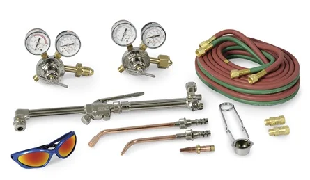
High-pressure gages for gases at 1,500 PSI and greater should be equipped with flow restrictors to moderate flow into the gage when flow begins.
Installed between hoses and torch or between hoses and regulators, check valves prevent the reverse flow of gas. Mounted on regulator outlets, flashback arrestors stop flashback, a high-pressure flame that runs from the torch tip back into the cylinder.
Hoses for OFW are limited to working pressures of 200 PSI. Four sizes are standard, from 5 /16- to 5 /8- in. inside diameter. Larger diameters offer less resistance to gas flow-they should be used when installations call for long hoses. Flexible and easy to handle, small-diameter hoses allow welders to maneuver around complex weldments with intricate details.
Pressure gauges for gases at 1,500 PSI and higher should be equipped with flow restrictors to moderate flow into the gage when flow begins. Regulators come with threaded connections, stipulated by CGA specifications for attachment directly to gas containing cylinders. Most fuel-gas regulators carry left hand threads; oxygen connections are right-handed.
Brazing Equipment and Consumables
Brazing joins materials, both metals and nonmetals, through the application of heat and a filler metal that melts at a temperature below the melting point of the materials being joined.
Process equipment includes torches, furnaces (vacuum or controlled atmosphere), induction coils, dip baths, and heating devices, for resistance brazing.
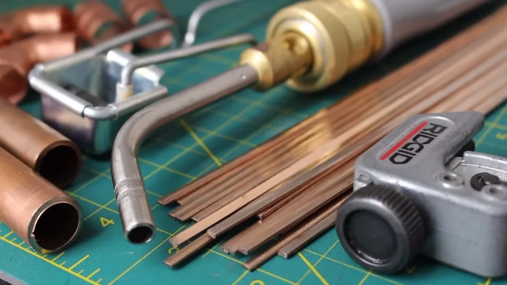
Brazing torches are the same as those used for gas cutting and welding operators fit brazing tips at torch ends. All commercial gas mixtures can be employed as fuel; oxyacetylene and oxygen-natural gas are used most often.
Brazing fillers come in wire, foil, rod, preforms, or paste, covered by AWS specs. Filler metals include Bag fillers (ferrous parts); or BCuP, BCu, or RBCuZn fillers for brazing copper parts. Baths for brazing carbon and low-alloy contain fluxing agents such as borax or cryolite.
Powered by electricity, gas, or oil, brazing furnaces provide air-tight chambers holding a vacuum or a controlled atmosphere of high-purity gas, inert or reducing. The AWS Brazing Handbook specifies 12 atmospheres for furnace brazing. induction brazing employs electrically powered induction coils to surround and heat joint sites.
For dip brazing, brazements sit in a heated bath, either of molten filler metal or a flux bath of molten salt-brazing alloys come as preplaced filler-metal preforms.
Resistance brazing places the workpiece, with filler metal preplaced, in an electrical circuit. Electrodes contact the brazement to conduct heat into the work, or resistance of the brazement material generates heat. Electrodes are of copper alloys—RWMA (Resistance Welding Manufacturers Association) Class 2 chromium-copper and Class 14 refractory electrodes or of carbon-graphite or electrographite. Common fillers include BAg-1, -1A, -2, -7, -8, and -18, and BCuP 2, and -5. Refer to the AWS Brazing Handbook for classifications of brazing fluxes.


